Wheel Translator Board
Overview

The Wheel Translator takes the signal from 2 VR sensors mounted to a flywheel: one that senses the flywheel gear teeth and one that sense TDC of cylinder 1 (or any other single event per engine rotation). With these signals, it generates a missing-tooth wheel crank signal by dividing the gear teeth number by a configurable number and synchronizing the generated signal using the TDC signal. This crank signal is directly usable by the Megasquirt CPU (MS1 or MS2).
This is a small board (1"x4") that fits into the last slot of the top half of the standard MegaSquirt enlosure. It can also be mounted directly to the case using the 4 mounting holes. It has 2 VR conditioner circuits using LM1815s, 1 Hall sensor opto-isolator circuit, and a CPU.
The VR conditioner circuits are based on the circuits given in the MS1/extra manual: see here. The Hall sensor opto-isolator circuit is the same as the MegaSquirt V3.0 circuit and it can be configured as either of the first two schematics presented here.
The thread discussing the board can be found here.
The initial version of the BOM is available here.
More information to come.
Assembly
Assembly instructions to come.
Setup
Divider Setup
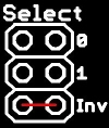
The divider can be set to divide by 2, 3, 4, or 5. This is done using the "Select" header as shown below.
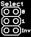 To divide by 2 leave both the 0 and 1 positions without any jumper.
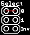 To divide by 3 put a jumper in position 0 and leave position 1 free.
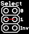 To divide by 4 put a jumper in position 1 and leave position 0 free.
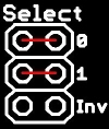 To divide by 5 put a jumper in both the 0 and 1 positions.
Crank Signal Inversion
To invert the crank signal, put a jumper in the "Select" header as shown below. This should not be needed if the MegaSquirt is configured appropriately.
Opto-isolator Circuit Setup
The opto-isolator circuit for the hall sensor can be configured in two different ways as shown below. For more information about the opto-isolator circuit, please refer to the Megamanual. The two configurations options correspond to the first 2 schematics in the Megamanual. If the camshaft Hall sensor is not used or the MegaSquirt board opto-isolator circuit is used then this can be ignored.
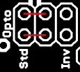 To set the opto-isolator circuit in the standard MegaSquirt way, put jumpers as shown here.
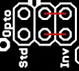 To set the opto-isolator circuit to produce an inverted signal, put jumpers as shown here. This is referred to as the MSnS-E modification in the Megamanual.
Pullup Setup
The crank and cam signals can be configured to generate either a 5V or a 12V signal. At the moment, there is not reason to generate a 12V signal so the pullup must be configured with a 5V pullup as shown below.
 To set pullups to 5V, put jumpers as shown here.
Connections
To connect the Wheel Translator Board to the MegaSquirt and to the external components, the board header shown below is used.

The VR1 and VR2 pads are connected to the 2 flywheel gear VR sensors. VR1 is used for the gear teeth sensor and VR2 is used for the TDC sensor. The positive side of both sensor must be used for these connections while the negative side of the sensors should be connected to the MegaSquirt's external ground.
The Hall pad is used to connect the camshaft Hall sensor to the on-board opto-isolator circuit input. If the MegaSquirt's opto-isolator circuit is used or if the camshaft signal is not needed, this pad and the Cam pad are left unconnected.
The Crank pad is connected to the MegaSquirt tach signal input. On the V2.2 board, this is pin 6 of U4. On the V3.0 board, this is the TSel pad.
The Cam pad is connected to the Megasquirt second VR input. The position of this input depends on which board and which CPU are used. With MS2, it also depends on which firmware is used. For MS1/extra, the Cam pad is connected to the pin 11 of the CPU. With the V2.2 board, you have to connect directly to the pin. With the V3.0 board, the connection is done through JS8. The MS2 setup is to come later.
The 12V pad should be left unconnected with the current application. The 5V pad is connected to a convenient 5V point on the board: for the V3.0 board, the proto area has a 5V pad, while on the V2.2 board, the voltage regulator (U5) can be used directly. The GND pad must be connected to the MegaSquirt ground: again, the proto area and the voltage regulator can be used.
It is theoretically possible to use the MegaSquirt V3.0 VR circuit as the input to the Wheel Translator CPU but this is yet to be tested. The way to connect this setup will come later.
Ordering
The Wheel Translator is only available as a partial kit which includes a board and a programmed CPU. The partial kits are available at US$24 per partial kit plus shipping. Shipping for up to 2 partial kits is US$4.50 in North America and US$7.50 in Europe. This is for regular mail from Canada.
Please note that regular mail service to the US has been quite irregular. The delivery time has been from less than 2 weeks to more than 4 weeks. If this is not acceptable, you can request Xpresspost service which will speed up delivery but will cost an additional US$15. Contact me for details and price.
I only accept Paypal.
You can contact me through PM at the msextra forum where my user name is racingmini_mtl
or by email: boards at jbperf.com