Peak&Hold Injector Driver Board for Megasquirt
Overview

Following the development of the hi-resolution MS1/extra code and for a future version of MS2/extra code (and MS3?), I have designed a small daughterboard that has 4 peak and hold injector drivers.
Since the hi-res MS1/extra code can't do a PWM signal on the injectors, the only solution with the standard MS injector drivers is to either use hi-z injectors or use inline resistors. This board allows the use of low-z injectors without any resistors and without setting up any PWM parameter since the chip (LM1949) the board is based on takes care of setting the current correctly no matter what the battery voltage is or what injector is there. The LM1949 datasheet is available here.
However, these drivers can only handle a single injector so the board can be used for engines with up to 4 injectors. For more injectors, more boards can be used.
I've designed the board such that there is one input per driver so each injector can be controlled by either of the 2 available MS injector channels (and this will allow 4 independent injector channels in the future MS2/extra code). Also, there is a single active flyback circuit for the 4 drivers as per Bruce's recommendation. The board layout assumes that the board will be used in the highest slot of the standard MS case with the 5 TO220 transistors bolted to the case. The board measures 4" by about 1.1" which means it fits well in the case slot and is short enough to allow more than one board to be used. The current BOM is here. It should be noted that if you are building a new board, all the injector driver parts are no longer needed so there could be some cost reduction there.
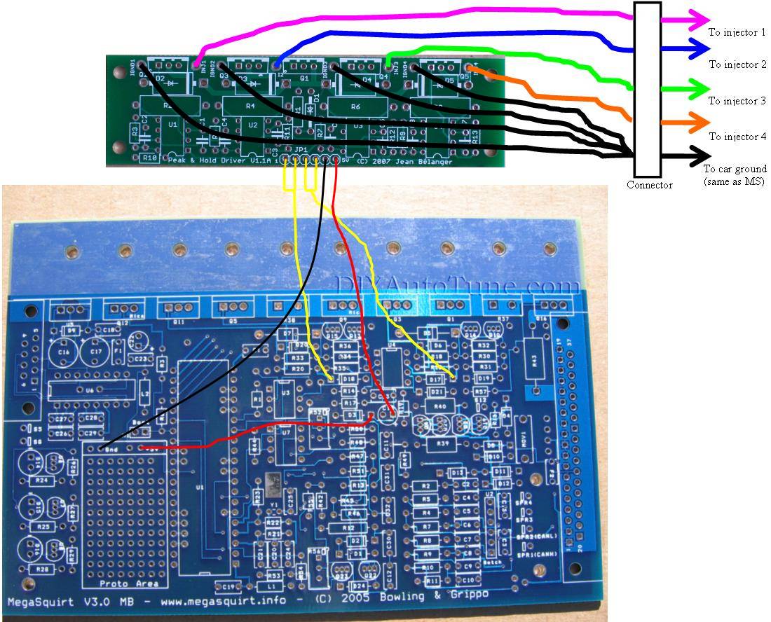
This shows how to connect the board.
Here is a picture of an assembled board in the highest slot of the case.
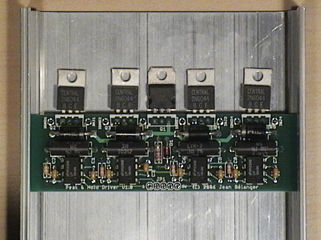
This shows how two boards can overlap when installed in the case.
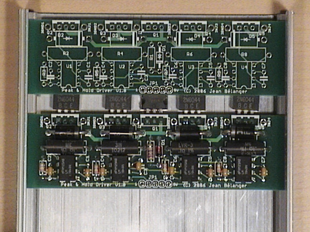
The thread discussing the board can be found here.
NEW! The V1.1A board is now available.
The V2.0.1 board information can be found here. The V2.0.1 board is designed as a stand alone injector driver box to be used with any ECU with grounding injector control.
Assembly
The latest BOM can be found here. To order directly from Digikey, click here or get the components with the board here.
Install all components on the top and solder on the bottom except for the 5 transistors which are inserted from the bottom and soldered on the top.
- Install U1-4
- Install R2-R4-R6-R8
- Install D2-5
- Install the other resistors, capacitors, and diode.
- Bend the leads of the transistors to insert them from the bottom of the board. Insert the transistors in the board without soldering them and slide the board in the last slot of the case half to position the transistors correctly. Mark the case and drill the holes. Screw the transistors to the top of the case and solder them to the board.
For final assembly, make sure to put the mica insulators between the transistors Q2-5 and the case and to apply heat grease on both sides of the insulators. Make sure that the transistors Q2-5 are really insulated from the case by measuring that the resistance between the tab and the case is infinite (or at least many megaOhms). You may need to deburr the holes in the case to achieve that.
Installation
In TunerStudio, you need to set the turn off the PWM current limiting (if your hardware/firmware does not have an explicit way of turning this off, use 100% for the current limit and 25.5ms for the time threshold).
Note: The installation instructions below are only for non-sequential installation.
V2.2
Note: For sequential installation ignore the instructions below and refer to this.
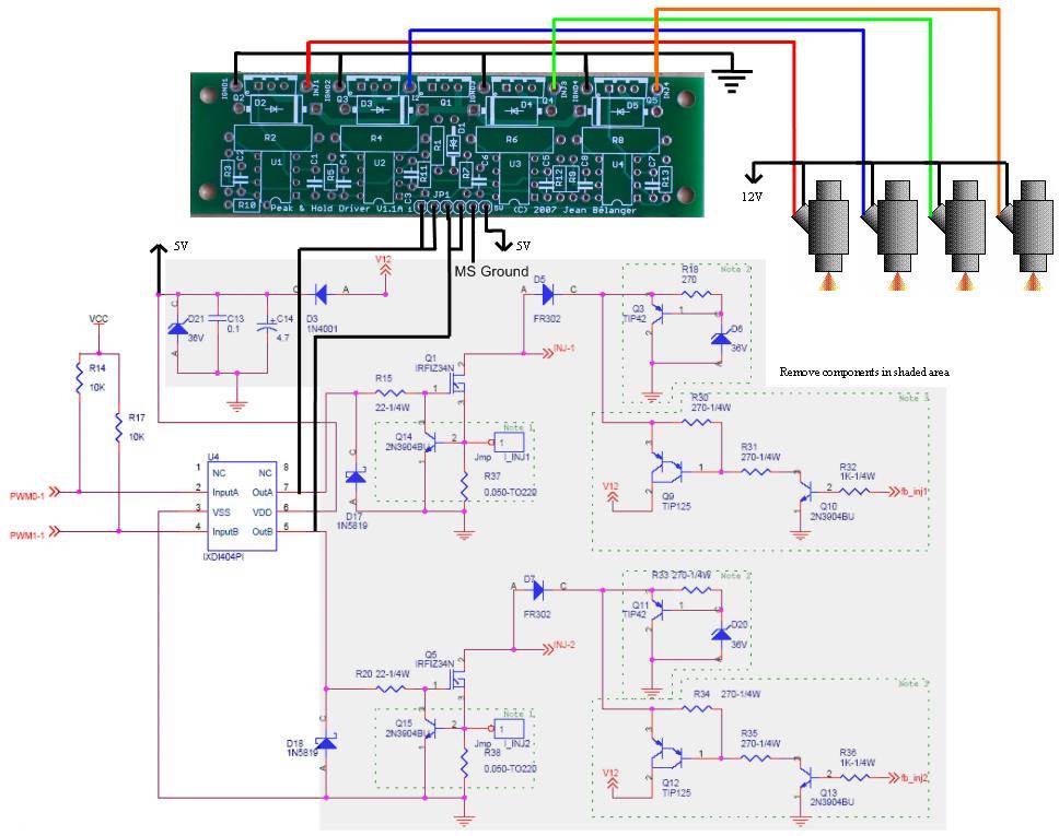
The injector control 1-4 wires are connected to the FET driver output in pairs. So you could connect injector control 1-2 to pin 7 and injector control 3-4 to pin 5. Pin 7 of the FET driver is connected to R12 and pin 5 is connected to R17. You want to remove R12 and R17 as well as Q2, Q7, D22, D23, Q1, R32, and D21.
You also want to remove C29, C30, and D20 and connect 5V to the power supply pin of the FET driver (pin 6). You can use the + side of C30 for that. 5V is available at the top side of R30 and R31.
This diagram shows the connections and the components to remove.
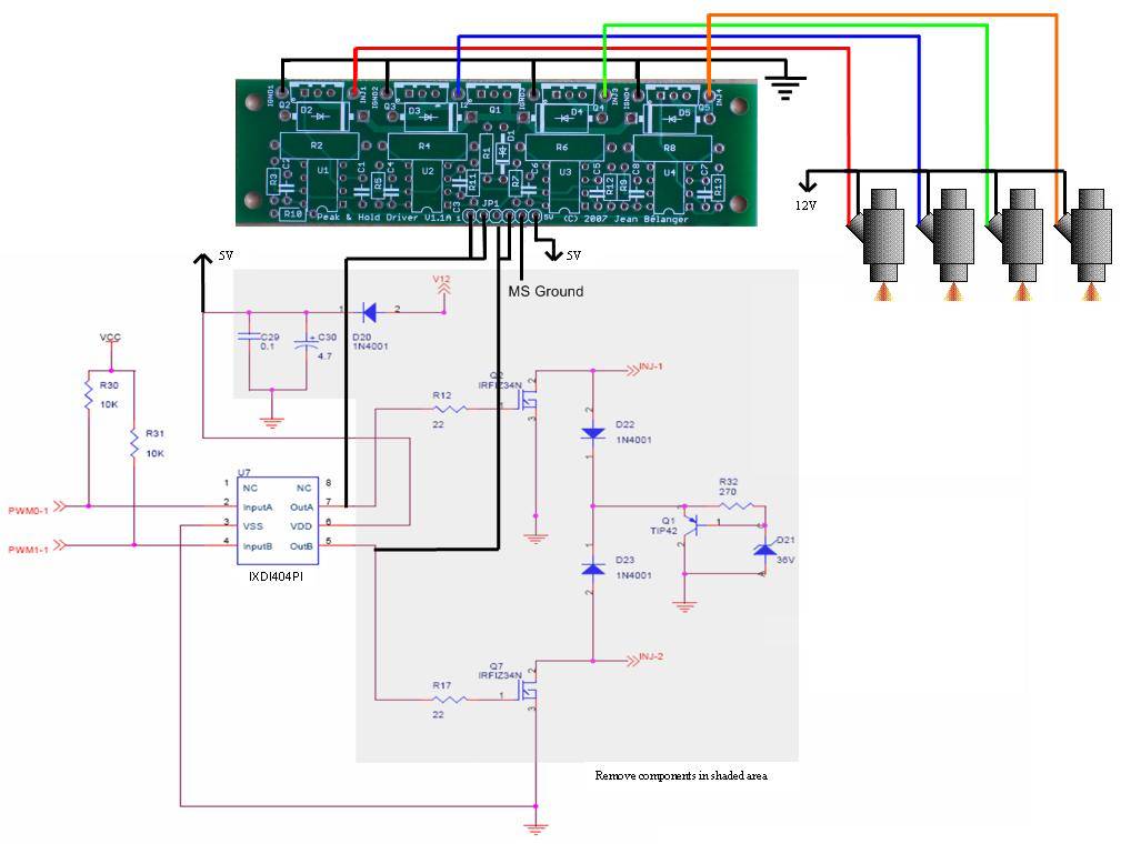
This assumes that you have the IXDI404 FET driver and not the MC34151. If that's not the case then you will need another solution because the MC34151 is not designed to work at 5V. Contact me if it's your case.
There are a few ways to connect the board to the injectors. Here are a couple of examples for a single board and 4 injectors: using the standard MS injector pins on the DB37 and an additional connector and using only an additional connector. Multi-board installations and installations with a different number of injectors can use similar connections.
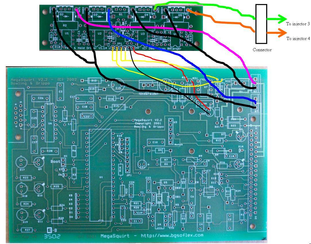
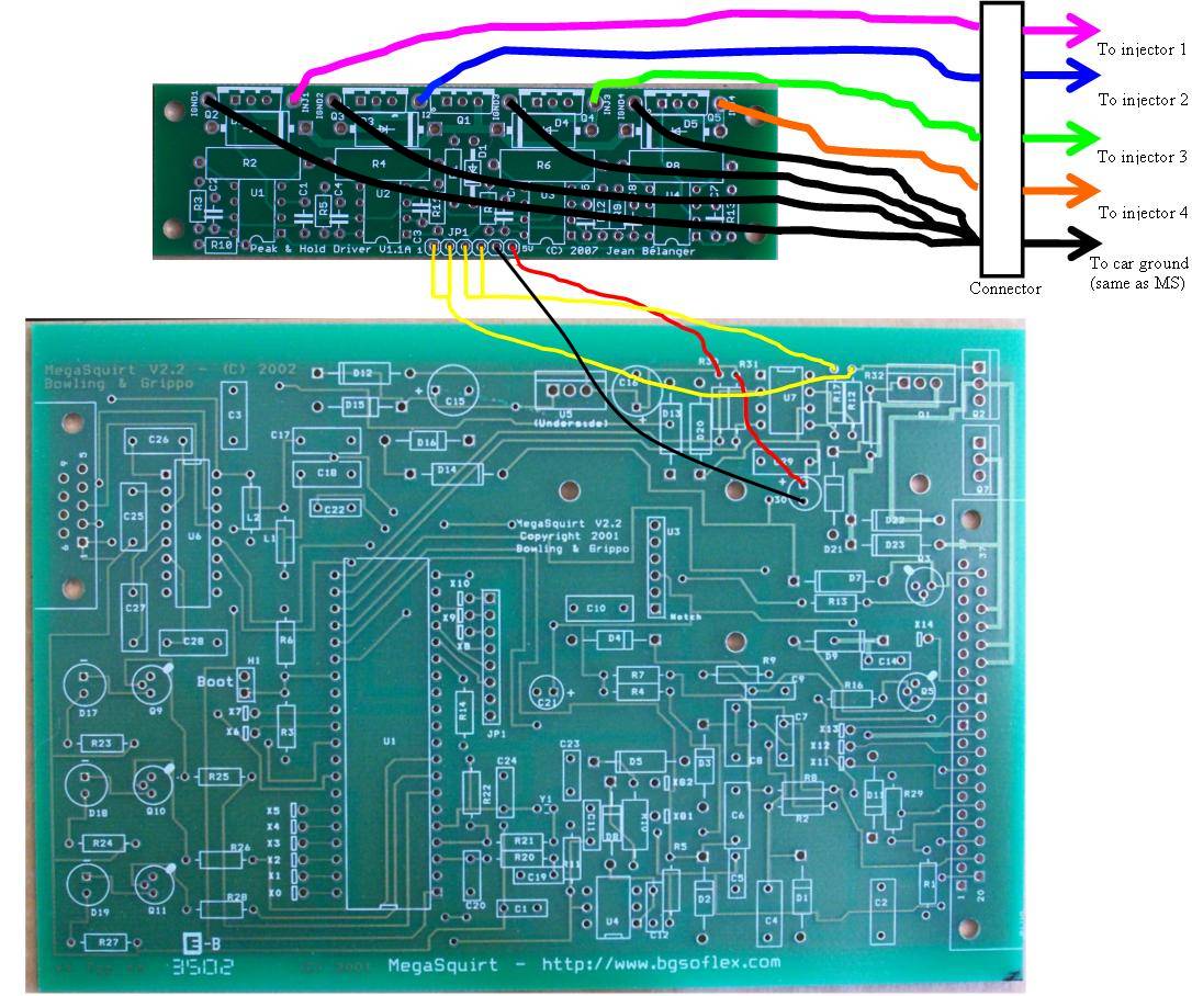
V3.0
Note: For sequential installation ignore the instructions below and refer to this.
The parts you no longer need are:
D3, D5, D6, D7, D17, D18, D20, D21, C13, C14, Q1, Q3, Q5, Q9, Q10, Q11, Q12, Q13, Q14, Q15, R15, R18, R20, R30, R31, R32, R33, R34, R35, R36, R37, R38
The parts you absolutely need to remove are the parts directly connected to U4 which are: D3, D21, C13, C14, D17, D18, R15, R20. The other parts could be left on the board if you are not going to use the DB37 pins for the injectors. But it's probably best to remove all unneeded components.
You will need to connect 5V to pin 6 of U4 (you can use the banded side of D21 or D3 or the + side of C14 for that connection). The 2 outputs of U4 are at pins 5 and 7 and are connected to the p&h boards (you can use the banded side of D17 and D18 for those connections).
This diagram shows the connections and the components to remove.
There are a few ways to connect the board to the injectors. Here are a few examples for a single board and 4 injectors: using the standard MS injector pins and spare pins on the DB37, using the standard MS injector pins on the DB37 and an additional connector, and using only an additional connector. Multi-board installations and installations with a different number of injectors can use similar connections. Note that the use of the DB37 spare pins (SPR1-4 and IAC1A-2B) require wires on the bottom of the board to go directly to the DB37 because the board traces are not big enough to handle the injector current.
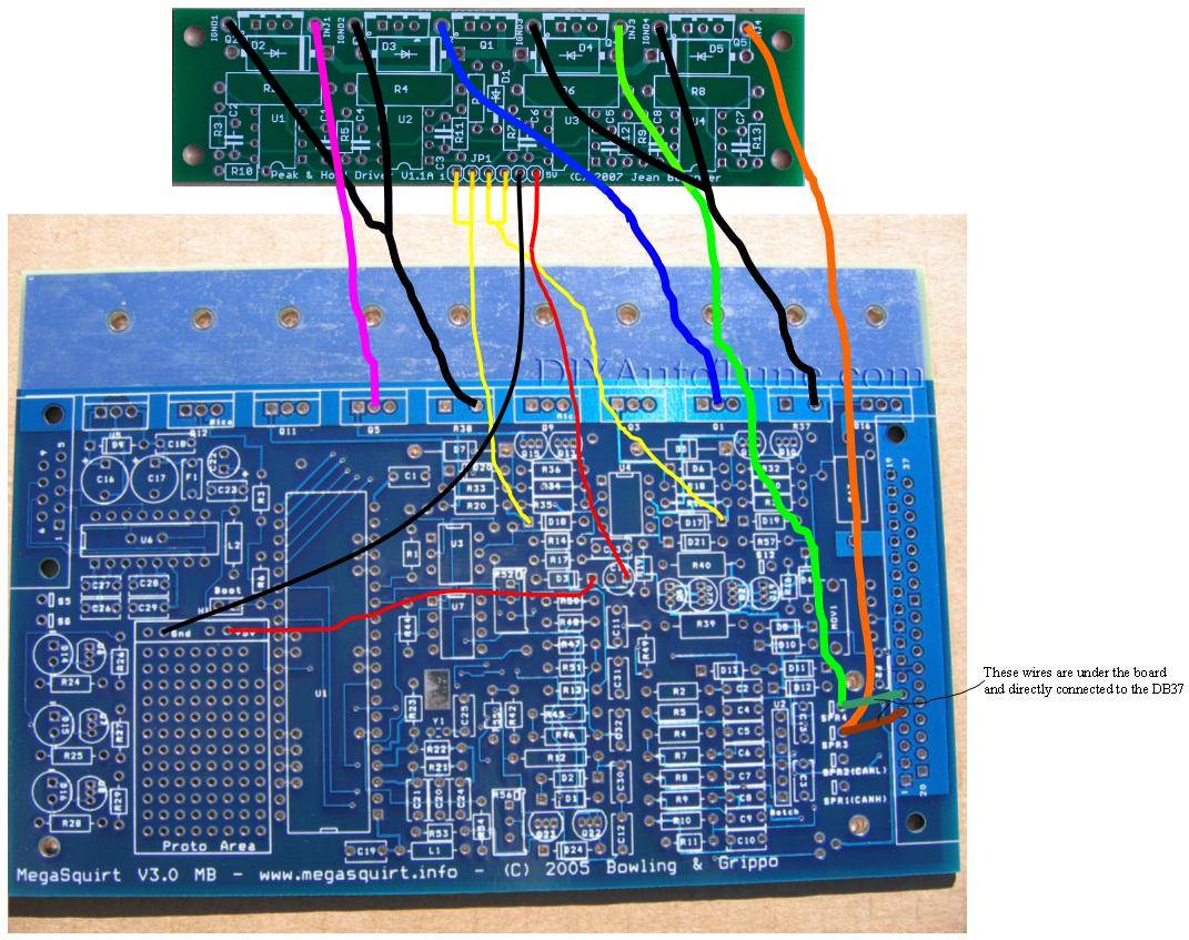
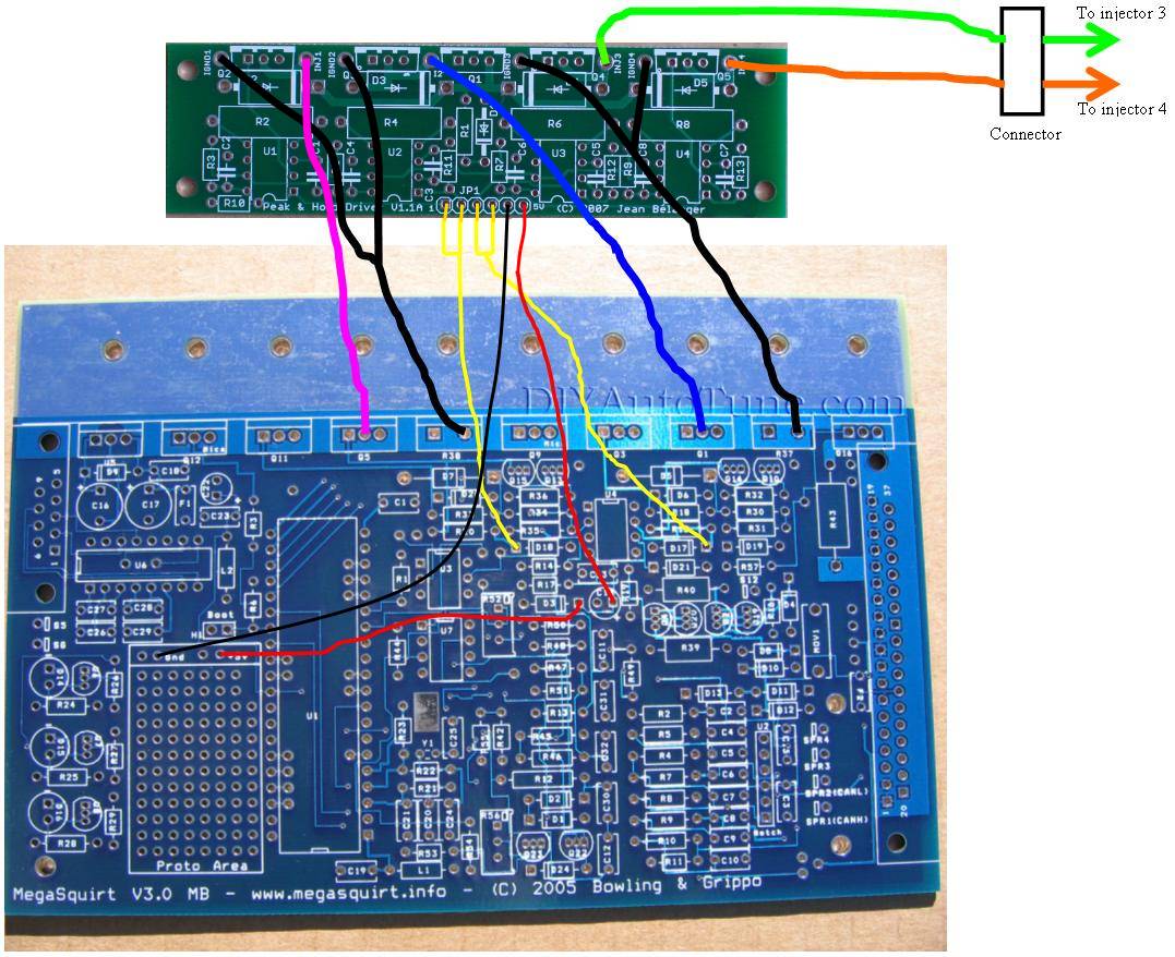
V1.1 P&H Board
The v1.1 p&h board has an extra pad at the JP1 connector (6-pad connector at the bottom of the board). The next to last pad is the new pad which is a ground for the low-current devices on the board which is separate from the high-current injector grounds. This pad needs to be connected to a ground pad on the MegaSquirt board. Use the ground pad of one of the removed components shown in the diagrams above.
The resistors R10-13 are also new to the v1.1 p&h board. These resistors are not needed in the standard installations shown above. If you are doing such an installation leave these unpopulated. The resistors are only needed when connecting the p&h board JP1 inputs directly to the CPU pins as will be done with the extra injector channels used by the sequential code of the MS2/extra 3.0 alpha.
V1.1A P&H Board (V1.1B)

The V1.1A board is essentially the same board as the V1.1 board but has 4 mounting holes to allow different options for board installation. It has the same features and components as the V1.1 board.
The mounting holes allow the board to be mounted in a non-standard case or to be mounted in a standard case but directly to the case instead of being in one of the slots. The board can be mounted in either case half and, using the appropriate standoffs, could be made to fit under the MS board. For that last option, make sure to trim the leads sufficiently on the MS board and the P&H board to prevent any interference between the boards and to prevent shorting between the boards and shorting between the P&H board and the case.
The mounting holes do not interfere with the standard board installation in the top slot of the standard MS case.
The V1.1B board is identical to the V1.1A except for some routing changes which do not change the functionality or the external appearance.
Ordering
The boards are available at US$18 per board plus shipping. Shipping for up to 4 bare boards or 1 complete kit is US$8.50. This is for regular mail shipping from Canada which means there is no insurance and no guarantee on the delivery time.
US buyers: Please note that, as of February 1st 2025, boards shipped to the US might be subject to a tariff. This will be charged to you by your government so we have no control on the amount or how and if this is charged to you. This is basically a sales tax on you, the consumer, by your own government.
Canadian buyers may want to contact me directly (orders at jbperf.com) for alternative payment options in Canadian funds, such as Interac, together with a lower shipping cost.
Kits are no longer available. Only the bare boards are available below.
Sales are suspended temporarily due to the possible upcoming CanadaPost strike.
There are quantity discounts: contact me for details.
You can contact me through PM at the msextra forum where my user name is racingmini_mtl
or by email: boards at jbperf.com