I/O Extender Board v1.0 for M2/Extra and MS3
Information about the TinyIOx board is available here.
Overview


Jumpers to connect circuits to the CPU and DB37 connector

Jumpers to connect circuits to the CPU

Jumpers to connect circuits to the DB37 connector

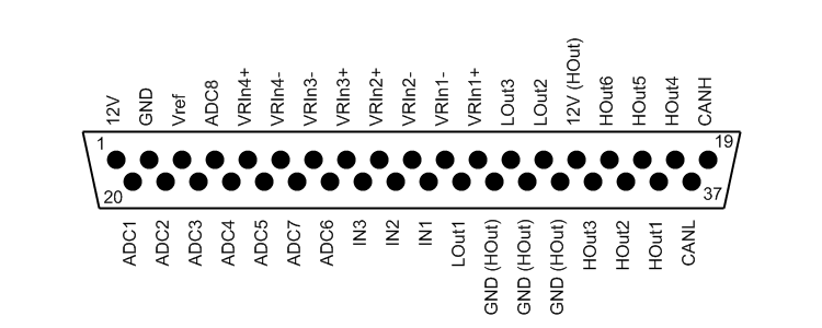
DB37 pin out (looking at the male connector on the board) for V1.1 and V1.2 boards
For the V1.0 pin out have a look here
Hardware Configuration
High Current Outputs

High Current Outputs

High Current Outputs Schematic

High Current Driver


Low Side Driver
High Side Driver
| Circuit | Default CPU Port | DB37 Pin (Hardwired) | Timer |
|---|---|---|---|
| HOut1 | PTD5 | 36 | Timer 1 Channel 3 |
| HOut2 | PTD3 | 35 | Timer 1 Channel 1 |
| HOut3 | PTD2 | 34 | Timer 1 Channel 0 |
| HOut4 | PTD1 | 18 | Timer 2 Channel 1 |
| HOut5 | PTL0 | 17 | - |
| HOut6 | PTG4 | 16 | - |
Low Current Outputs

Low Current Outputs

Low Current Outputs Schematic

Low Current Driver

Low Current Driver Jumpers

Low Current Driver with 5V Pullup

Low Current Driver with 12V Pullup
| Circuit | Default CPU Port | DB37 Pin | Timer |
|---|---|---|---|
| LOut1 | PTJ6 | 30 | - |
| LOut2 | PTJ5 | 14 | - |
| LOut3 | PTJ4 | 13 | - |
Active High Inputs

Active High Inputs

Active High Inputs Schematic
| Circuit | Default CPU Port | DB37 Pin | Timer |
|---|---|---|---|
| IN1 | PTK7 | 29 | - |
| IN2 | PTK6 | 28 | - |
| IN3 | PTK5 | 27 | - |
VR Conditioners

VR Conditioners

VR Conditioners Jumpers

VR Conditioners I/O
| Circuit | Default CPU Port | DB37 Pin | Timer |
|---|---|---|---|
| VR1 | PTJ0 | 5 (+) 6 (-) | Timer 3 Channel 0 |
| VR2 | PTJ1 | 7 (-) 8 (+) | Timer 3 Channel 1 |
| VR3 | PTJ2 | 9 (+) 10 (-) | Timer 3 Channel 2 |
| VR4 | PTJ3 | 11 (-) 12 (+) | Timer 3 Channel 3 |
ADC Conditioners

ADC Conditioners

ADC Conditioners Schematic
Please note that the V1.0 board has an error in that the input and output of the ADC conditioners have been inverted. This is only important if using the bias or weak pull down resistors (e.g., R40, R42) which would need to be soldered to the DB37 side of the circuit instead of the CPU side as the board is done.

ADC Conditioners Jumpers To CPU
| Circuit | Default CPU Port | DB37 Pin (Hardwired) | Timer |
|---|---|---|---|
| ADC1 | PTB2/ADP10 | 20 | - |
| ADC2 | PTC3/ADP19 | 21 | - |
| ADC3 | PTB3/ADP11 | 22 | - |
| ADC4 | PTB4/ADP12 | 23 | - |
| ADC5 | PTC4/ADP20 | 24 | - |
| ADC6 | PTA5/ADP5 | 26 | - |
| ADC7 | PTB5/ADP13 | 25 | - |
| ADC8 | PTA6/ADP6 | 4 | - |
Software Configuration
The TunerStudio ini file is available here. Using Megatune is possible but will require editing the ini.
Base Configuration

The tool below gives the resulting PWM frequency when setting the timer parameters for the PWM outputs used for idle valve and boost control. It also gives the maximum interval that can be measured when using the timer channel as an input like it's done for the 4 VR conditioners. It is also possible to use the this spreadsheet to find the correct combination for a desired PWM frequency.
It should be noted that all channels of the same timer will have the same frequency (but their own separate duty cycle). If different frequencies are needed for outputs such as PWM idle valve and boost control, these 2 functions need to be put on CPU pins which are mapped to different timers. So it would be possible to put the PWM idle valve on the high current driver 1 (HOut1) which is mapped by default to PTD5 (timer 1 channel 3) and put boost control on the high current driver 4 (HOut4) which is mapped by default to PTD1 (timer 2 channel 1). Then timer 1 is configured according to the needs of the PWM idle valve and timer 2 is configured according to the needs of the boost controller.
ADC Inputs

The ADC settings shown above are for the default ADC channels when using the jumpers for the on-board circuits. The numbers go from 0 to 23 and correspond to the CPU channel numbering. The ADC resolution can be set to 8, 10, or 12 bits. If the ADCs will be used for logging purposes only then any resolution can be selected. If they will be used as inputs for MS2/Extra parameters (e.g., barometric correction), 10-bit resolution must be chosen since this is the resolution expected by the code.
See the expansion section below for the ADC channels position on the expansion ports.
PWM Inputs

The input PWM parameters are hardcoded in the current code version. If they are enabled, the 4 circuits will use the default CPU ports configured as input capture on the rising edge. The 16-bit values will be put in the 4 variables for transmission to the MS2. The timer used is timer 3 and the prescale is set in the base settings window.
Generic Inputs/Outputs

The configuration shown above sets the port 1 data received from the MS2 as a set of digital outputs to the high current drivers. The channels (CPU pins) shown are the ones for the default on-board high current drivers 1 to 6 set as low-side drivers and with the jumpers. Any change made in this window requires a power cycle to take effect since the pin initialisation is only performed on power up.

The configuration shown above sets the port 2 data received from the MS2 as a set of digital outputs to the low current drivers. The channels (CPU pins) shown are the ones for the default on-board low current drivers 1 to 3 with the jumpers to the CPU. Any change made in this window requires a power cycle to take effect since the pin initialisation is only performed on power up.

The configuration shown above sets the port 3 data as a set of digital inputs from the active high inputs to be sent to the MS2 upon request. The channels (CPU pins) shown are the ones for the default active high inputs 1 to 3 with the jumpers to the CPU. Any change made in this window requires a power cycle to take effect since the pin initialisation is only performed on power up.
Example configurations
MS2/Extra CAN polling configuration

The configuration shown above is for the current I/O Extender firmware (0.0.1) with the default configuration: the CAN id is 5 and the table numbers and offsets are as shown.
The remote ports can be set as either inputs or outputs. When set as 2 inputs and 1 output, port 1 is the output and port 2 and 3 are inputs. When set as 1 input and 2 outputs, ports 1 and 2 are outputs and port 3 is the input. Each port can be set as 8 digital values (one bit per I/O) or as a single value (a single I/O for the entire port). The single value is only valid as an output and is used for passing the PWM value for the PWM idle valve and/or the boost controller.
When at least one of the ports is set as an 8 digital value output, the generic spare ports can use one of these remote output ports instead of the MS2 spare output ports. However, since this configuration window for the spare ports is hardcoded in both Megatune and TunerStudio making it impossible to change the displayed ports, the configuration will still show the MS2 ports even though the remote port on the I/O Extender will be used. This means that the mapping shown in the table below will be done. It should be noted that at this time all the spare ports are either on the MS2 or on the I/O Extender. It is not possible to have a mix of MS2 and I/O Extender spare port configuration.
| MS2 Port Displayed | Actual I/O Extender Port Used |
|---|---|
| PM2 - FIdle | Selected Port Channel 1 |
| PM3 - Injection LED | Selected Port Channel 2 |
| PM4 - Accel LED | Selected Port Channel 3 |
| PM5 - Warmup LED | Selected Port Channel 4 |
| PT6 - IAC1 | Selected Port Channel 5 |
| PT7 - IAC2 | Selected Port Channel 6 |
| PA0 - Knock Enable | Selected Port Channel 7 |
PWM Idle Valve
")

The MS2/Extra windows above shows the selection of the I/O Extender port 1 for PWM idle port and the remote port 1 as being a single value output. It also show that the frequency selection is grayed out since the PWM frequency is chosen on the I/O Extender and only the duty cycle is transmitted. The 2 I/O Extender windows below show the needed settings to configure the I/O Extender to perform the PWM idle valve control (on HOut1 using timer 1 channel 3). In this example, the chosen PWM frequency is 300.5Hz (16MHz bus speed with a 16 prescale and a PWM frequency divider of 12). The tool above can be used to compute the frequency.


Boost control

The MS2/Extra windows above show the selection of the I/O Extender port 2 for boost control remote port and the remote port 2 as being a single value output. It also show that the frequency selection is grayed out since the PWM frequency is chosen on the I/O Extender and only the duty cycle is transmitted. The 2 I/O Extender windows below show the needed settings to configure the I/O Extender to perform the boost control function (on HOut4 using timer 2 channel 1). In this example, the chosen PWM frequency is 30Hz (16MHz bus speed with a 16 prescale and a PWM frequency divider of 129). The tool above can be used to compute the frequency.


Spare ports

The MS2/Extra windows above show the selection of the I/O Extender port 3 for the generic spare ports and the channel 1 of port 3 (displayed as PM2 - FIdle as per the table above) as being triggered when RPM goes above 4000RPM. The I/O Extender window below shows the channel 1 will use the low current driver 1 (LOut1 on PTJ6) which means that this will be activated above 4000RPM. It also shows that the other spare ports will use HOut5 (PTL0), LOut2 (PTJ5), HOut2 (PTD3), HOut3 (PTD2), LOut3 (PTJ4), and HOut6 (PTG4) as per the HOut and LOut tables above.

Barometric correction


Second O2

Table switching

The MS2/Extra windows above show the I/O Extender port 3 being configured as an input with 8 digital signals and the channel 1 (bit 0) of port 3 as being used for fuel table switching and the channel 2 (bit 1) of port 3 as being used for spark table switching. The I/O Extender window below shows the channel 1 will use the active high input 1 (PTK7) and the channel 2 will use the active high input 2 (PTK6).
Launch control

N2O control


Expansion

JP1 Expansion port pin out

JP2 Expansion port pin out

JP3 Expansion port pin out

JP4 Expansion port pin out

JP5 Expansion port pin out