Sequential Injection Code for MS2
Overview
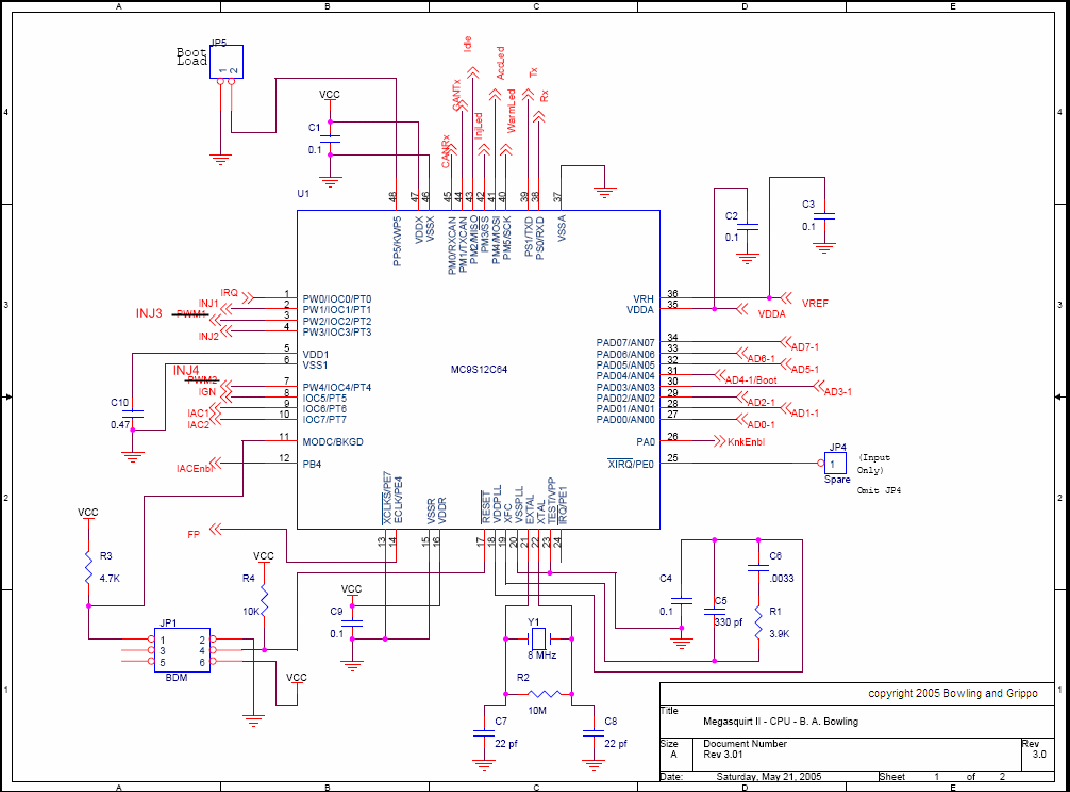
This code is based on the MS2/Extra code 2.1.0 and is part of the alpha 3.0 version. It can perform sequential and semi-sequential injection and allows the use of 2 additional injector channels. It requires a small modification to the MS2 card to make use of the additional injector channels as shown here. All the other code features are the same as the current MS2/Extra code so the corresponding documentation should be used to configure those.
The latest code is available here. Discussion on the code is done in this thread, this thread, this thread, and this thread.
The code will do sequential injection for engines with up to 4 cylinders (with the additional injector channels) and semi-sequential injection for engines with up to 12 cylinders. The number of injection pulses per engine cycle is automatically computed by the code based on the number of cylinders, the number of injector channels, the presence of a cam sensor, and the use of staged injection. Sequential injection has a single injection pulse per engine cycle and semi-sequential has up to 6 pulses per cycle depending on the configuration.
The table below shows the number of injection pulses per engine cycle computed by the code.
| No Staging | Staging |
|---|
| # Cyl | Cam trigger | # Inj | # Squirts per 720 deg | # Inj | # Squirts per 720 deg |
|---|---|---|---|---|---|
| 1 | 1 | 2 | 2 | 2 | |
| 1 | * | 1 | 1 | 2 | 1 |
| 2 | 1 | 2 | 2 | 2 | |
| 2 | * | 2 | 1 | 4 | 1 |
| 3 | * | 1 | 3 | 2 | 3 |
| 3 | * | 3 | 1 | - | - |
| 4 | - | - | 2 | 4 | |
| 4 | 2 | 2 | 4 | 2 | |
| 4 | * | 4 | 1 | - | - |
| 5 | * | 1 | 5 | 2 | 5 |
| 6 | 1 | 6 | 2 | 6 | |
| 6 | * | 2 | 3 | 4 | 3 |
| 6 | 3 | 2 | - | - | |
| 6 | * | 3 | 2 | - | - |
| 8 | - | - | 2 | 8 | |
| 8 | 2 | 4 | 4 | 4 | |
| 8 | 4 | 2 | - | - | |
| 10 | 1 | 10 | 2 | 10 | |
| 12 | 2 | 6 | 4 | 6 | |
| 12 | 3 | 4 | - | - |
There are 2 injection modes specifically designed for siamese-port engines such as the A-series engine of the classic Mini and the B-series engine of the MGB. Since these engines have 2 intake ports for a 4-cylinder engine with the cylinders paired having 180 and 540 crankshaft degrees between the firing events, there is a need to have injection timed in a very specific manner and two modes are provided to do semi-sequential injection which does not require a cam sensor and full sequential injection which requires a cam sensor. More information on the peculiarities of port injecting a siamese-port engine can be found here.
Configuration
The menu items to configure the sequential injection are located in the Advanced menu. "Sequential injection" is used to configure all the general aspects of sequential injection. The other menu items, greyed out in the picture below, are used to set the injection timing tables and the VE trim tables. The tables are also available under the "Tuning" menu. The doubling of the VE trim table menu items is due to having the choice between 12x12 and 16x16 tables (as for the standard VE tables).
It should be noted that the VE trim tables are not available when using Megatune due to limitations within the software. The use of TunerStudio is needed to have full access to the tables.
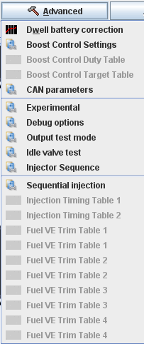
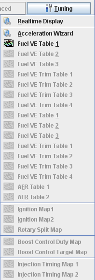
The picture below shows the sequential injection configuration window.
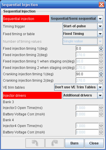
 The Sequential injection drop down list allows the selection of the sequential injection mode. Untimed injection is used to disable sequential injection. Sequential/Semi-sequential is used to enable sequential/semi-sequential injection for most engines.
Semi-sequential Siamese and Sequential Siamese are used to enable timed injection for siamese-port engines such as the classic Mini's A-series engine or the MGB's B-series engine.
 The Timing trigger list is used to set how the injection pulse will be located with respect to the injection timing trigger. Start-of-pulse means that the injection timing determines the start of the injection pulse. Mid-pulse means that the injection timing is located in the middle of the effective pulse. End-of-pulse means that the injection timing sets the end of the injection pulse.
The effecitve pulse in mid-pulse mode is the injection pulse without the opening time. This means that if the pulse width is 5ms and the opening time is 1ms, the injection pulse will start 3ms before the injection timing point and end 2ms after. Also, the end-of-pulse trigger is useful in case where it is desirable to have the injection all done before some event such as the valve opening. Mid-pulse is useful when the injection has to be done within a specific injection time window such as with the siamese-port engines.
 The injection timing can be set as a single value for all loads and RPM (Fixed timing) or it can be set in a table (Use table). The table is a 6x6 table and varies the timing according to load and RPM. Timing values are interpolated between table cells.
 When using the sequential siamese mode, the number of timing values can be set to Single value or Dual values. With a single value, the timing is the same for all cylinders while using dual values allows a different timing for the inner and outer cylinders.
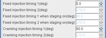 When using fixed timing, the injection timing can have 3 different values: one value for normal operation, one value when staging is active, and one value for cranking. The timing value can be from -360 to 360 degrees which covers the entire engine cycle range.
For sequential mode, the timing value is with respect to TDC on the power stroke when both valves are closed (same as ignition).
For sequential siamese mode, the timing is with respect to TDC on the intake stroke which is the start of the injection window for the outer cylinders. And the timing 2 values are only used in sequential siamese mode with the first timing value being for the outer cylinders (1 and 4) while the second is for the inner cylinders (2 and 3).
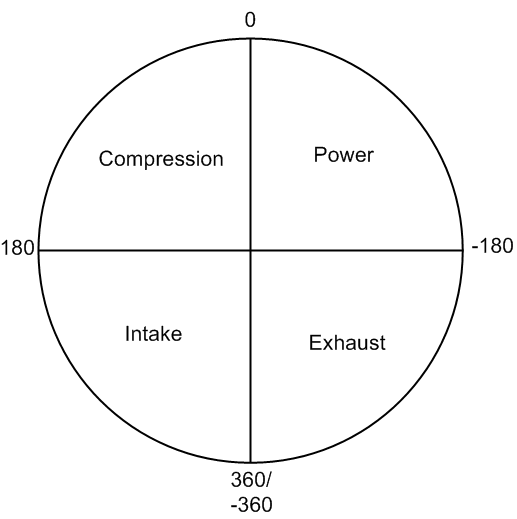
Sequential/Semi-sequential Timing
The image on the left shows how the timing values relate to the engine cycle. The timing value of 0 degrees corresponds to TDC between the compression and power stokes.
Positive values are for timing in advance of this point up to 360 degrees which corresponds to TDC between the exhaust and intake strokes with 180 degrees being BDC between the intake and compression strokes.
Negatives values are for timing retarded from the 0 degree point with -360 degrees being TDC between the exhaust and intake strokes and -180 degrees being BDC between the power and exhaust strokes.
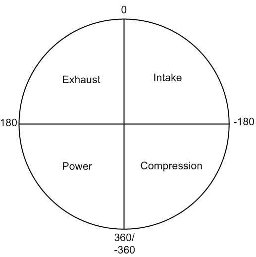
Siamese-port Timing
The siamese-port modes use a different reference point in the cycle due to the position of the injection window. The image on the right shows how the timing values relate to the engine cycle. The timing value of 0 degrees corresponds to TDC between the exhaust and intake strokes.
Positive values are for timing in advance of this point up to 360 degrees which corresponds to TDC between the compression and power stokes with 180 degrees being BDC between the power and exhaust strokes.
Negatives values are for timing retarded from the 0 degree point with -360 degrees being TDC between the compression and power strokes and -180 degrees being BDC between the intake and compression strokes.
 The pull down list shown on the left is used to enable the use of VE trim tables. There is one trim table per injector channel and they are the same dimension as the VE tables (12x12 or 16x16). The tables allow to modify the injector pulse width from -12.4% to 12.4% compared to the base pulse width computed from the main VE table.
 This item is used to allow the use of 2 additional injector channels. When Standard drivers is selected, the 2 standard MS injector channels are used. When Additional drivers up to 2 additional drivers are used. The hardware modifications needed are described in the section below.
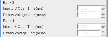 This is used to set the injector parameters when the additional injector channels are in use and different values are used for all injector channels (as selected in the injector characteristics of the Basic setup menu).
Board Modification and Connections for Additional Injector Drivers
To use the additional injector drivers, the MS2 card needs to be modified as shown below. This modification requires the removal of the MegaSquirt board clock circuit which is only used by the MS1 CPU. This also means that the board will no longer be usable with an MS1 CPU.
Also, the modification will require the use of 4 identical injector drivers. It would be possible to reuse the ones already on the MS board but it would require duplicating the circuits for 2 more drivers which would require a lot of board space. Two possible solutions are available: for low-impedance injectors, the peak&hold driver board can be used and for high-impedance injectors, the 4-channel driver board can be used. It is also possible to use similar circuits and simply install the components on the proto area of the V3 board or on a proto board and on the case.
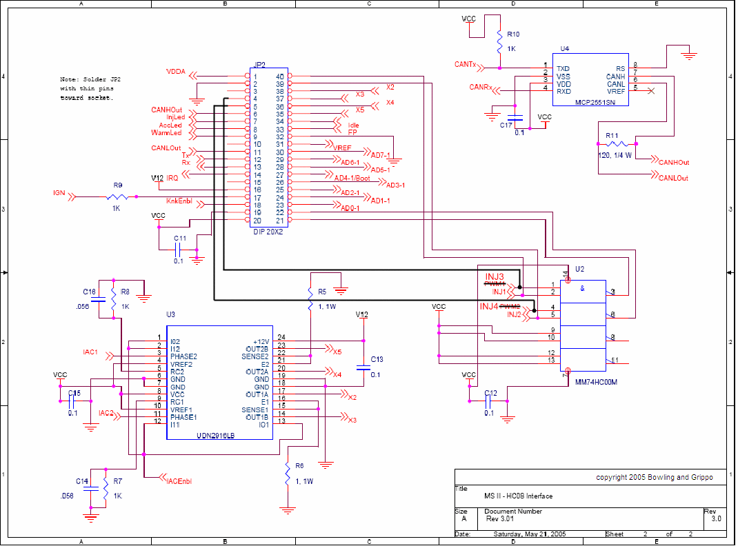
The picture below shows the modification which connects pin 1 of the NAND gate chip (U2) on the MS2 card to pin 4 of the 40-pin header and pin 4 of U2 to pin 5 of the header.
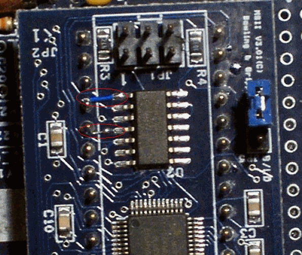
With that modification, pins 3 and 7 of the MS2 CPU can be used for injector channels 3 and 4, respectively, as shown below.
These new signals are taken at the input of the NAND gat chip since it a much more convenient location (closer to the header pins and more space to solder jumpers). The black lines in the schematic below show the new jumpers connection. It should be noted also that the CPU pins corresponding to injector channels 1 and 2 are already directly connected to the 40-pin header at pins 39 and 40.
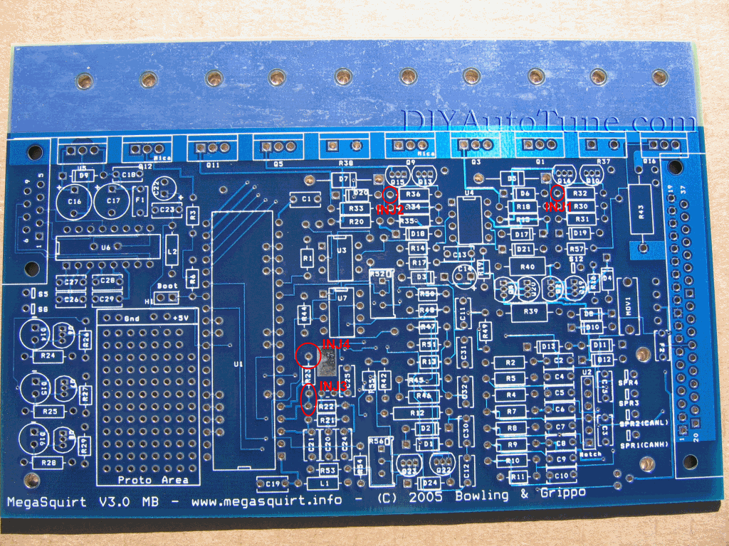
The picture below shows the placement on the V3.0 board of the 4 injector channels. The standard injector drivers components can be left on the board but will be unused and will not interfere with injector channels 1 and 2. The injectors channels 3 and 4 connect to pads originally used for the MS1 clock circuit and require the removal of those components for proper and safe operation. The injector channel 3 shows 2 pads because they correspond to the same electrical location (use either one). The components to remove are: R21,C20,C21,R22,R23,Y1,C24,C25.
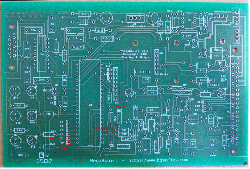
The picture below shows the placement on the V2.2 board of the 4 injector channels. The standard injector drivers components can be left on the board but will be unused. If the flyback board has been installed, it can be left or removed but will be unused and will not interfere with injector channels 1 and 2. The injectors channels 3 and 4 connect to pads originally used for the MS1 clock circuit and require the removal of those components for proper and safe operation. The injector channel 3 shows 2 pads because they correspond to the same electrical location (use either one). The components to remove are: R20,C19,C20,R21,R22,Y1,C23,C24.
