PWM Converter Board
Overview
Following discussions on the MS2/extra forum, I have designed a board which takes a PWM signal (such as the output for FIDLE or boost control the with MS2/extra code) and multiplies the frequency while keeping the same duty cycle without losing any precision. This allows people to control a device (solenoid, valve, motor) that requires a frequency higher than what the code can do or use a lower frequency in the code (with the associated higher resolution) and have the device work at a higher frequency.
The CPU on the board will read the PWM signal and keep the same duty cycle but multiply the frequency. It has been tested with the MS2/extra code from 11.1Hz to 78Hz with good results but it will work from about 8Hz to more than 300Hz. The output frequency can be chosen by setting jumpers and the resulting frequency multipliers can be 2, 4, 8, 16, 32, 64, 128, and 256. At an input frequency of 78Hz from the MS2 and a multiplier of 256, the PWM converter CPU will generate a 19968Hz PWM signal with a 0.25% resolution. So it's safe to say that any usable combination of input frequency and multiplier will not lose any precision. Also, the PWM duty cycle (and frequency) is updated for every cycle of the input signal so at 11.1Hz the output duty cycle is updated 11.1 times per second and at 78Hz the update is done 78 times a second. And the input is read with a 16-bit timer with 12 to 16 effective bits depending on the input frequency.
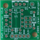
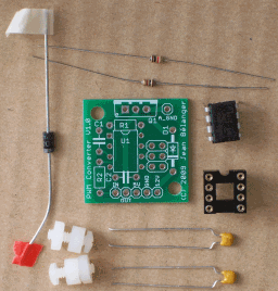
The board is 1"x 1", has 2 mounting holes and is shown at the top of the page. The kit includes all the components as shown below plus a TIP122 and mounting kit with insulator which are not in the picture. The kit includes a socket for the processor but its use is optional since it makes the completed board taller. Additional care must taken, if not using the socket, when soldering the CPU to the board since it is more sensitive to heat and static.
Note: The CPU socket is no longer provided with the kit.
The board has been tested on the MegaSquirt FIDLE and JS11 outputs with the FIDLE signal and the boost control signal. The board needs a 5V input signal and cannot take a 12V input signal so it cannot take one of the IAC outputs as its input. What could be done is using a voltage divider (2 resistors) to reduce the voltage. One thing that needs to be verified is if the UDN2916 can be fed with 5V instead of 12V (on JS9) which would make this an easy way to have a 5V signal.
Assembly
The assembly is simply a question of soldering all the components to the board except the TIP122. This will need to be soldered once the board positioning on the case has been established as described in the next section.
Before starting assembly, decide if you're going to use the CPU socket. As mentioned above, this is optional and will make replacing the CPU easier if needed and protect the CPU from the soldering heat. However, it will make the completed assembly taller which may cause some physical interference with other components depending on the location. Check where you want to install the board before deciding on the use of the socket.
If using the socket, solder that to the board first. If not, then solder the CPU. Solder the 2 resistors, the diode, and the 2 capacitors.
Note: The CPU socket is no longer provided with the kit.
It will be necessary to install the jumpers to obtain the desired frequency multiplier for the output PWM signal. The jumpers can be formed from the leads that were clipped off the resistors and capacitors during the assembly. The pictures below show the needed jumpers to obtain the desired multiplier.
| Jumpers | Multiplier |
|---|---|
 | 2 (no jumper) |
 | 4 |
 | 8 |
 | 16 |
 | 32 |
 | 64 |
 | 128 |
 | 256 |
This completes the assembly.
Installation
The first step is to decide where you're going to install the board. Then you will need two 0.125" (3.175mm) holes to mount the board. Use the board as the template. Then a hole needs to be drilled for the transistor. Make sure to deburr the hole to avoid any shorts between the transistor case and the MS case. The transistor is fitted to the board from the bottom so the leads are bent 90 degrees upward and the board is lowered on it. With the board attached to the case with the unsoldered TIP122's lead in their appropriate locations, drill a 0.125" hole in the case using the transistor as the template.
Once this is done, the TIP122 has to be mounted to the case using the insulator and mounting kit and the board lowered onto it and attached to the case. Then the TIP122's leads can be soldered to the board. After soldering, remove everything and clean the board of any flux. Reinstall to the case and put heat sink grease on the insulator on both the TIP122 side and the case side.
The wiring is the next and last step. Wire the IN pad on the board to the chosen output on the MegaSquirt board (FIDLE or JS11). Wire the OUT pad to the solenoid or valve to be controlled. This can be done through one of the spare pins on the DB37. Wire the 5V and GND pads to the power supply on the MS board. The 5V and GND pad on the proto area can be used for this. Wire the 12V and A_GND pads to the car battery (or equivalent). Again, spare DB37 pins can be used or the MS boards 12V and ground could be used. Noise could result from doing the latter so this has to checked.
Ordering
The boards are available only as complete kits for US$25 per kit plus shipping. Shipping for up to 2 complete kits is US$4.50 in North America and US$7.50 in the rest of the world. This is for regular mail shipping from Canada which means there is no insurance and no guarantee on the delivery time.
Please note that regular mail service to the US has been quite irregular. The delivery time has been from less than 2 weeks to more than 4 weeks. If this is not acceptable, you can request Xpresspost service which will speed up delivery but will cost an additional US$12. Contact me for details and price.
Note: You will need thermal grease and wires to complete the installation (not included in complete kit).
Due to a possible strike at CanadaPost, sales are suspended.
You can contact me through PM at the msextra forum where my user name is racingmini_mtl
or by email: boards at jbperf.com

