TinyIOx v1.0 Board
Overview
The TinyIOx is based on the smallest package from the CPU family used by the IOx (I/O Extender). So it has a small subset of the IOx:
- 9 ADCs
- 6 timer channels
- CAN
- 1 RS-232 port
- 1 I2C bus
- 2 spare digital I/Os
The RS-232 is connected to a 2.5mm jack for connecting to an LC1 chain. The TinyIOx communicates with an MS2 or MS3 through the CAN port.
And all the ports can be used as digital I/Os with the exception of the timer 1 channels which are used exclusively as PWM inputs. The timers channels can be used for either PWM outputs or for pulse signal (PWM) inputs such as speed sensors.
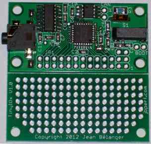
If you want to get the digital data from an LC1 or a chain of up to 16 of them, you can simply connect the TinyIOx to the CAN bus of your MS2 or MS3, power it from the 5V supply of your MS board and plug the LC1 chain to the 2.5mm stereo jack using the standard Innovate wire. This is what the board looks like:

TinyIOx V1.0 Board
The bottom part of the board is a prototyping area where circuits can be built to condition the input signals or to buffer/amplify the output signals. This part of the board can also be snapped off if not needed to minimize the space needed for installing the board.
The TinyIOx board is discussed on the forum here.
Board
The current V1.3 board has the same dimensions and pinout as the V1.0 board shown below.
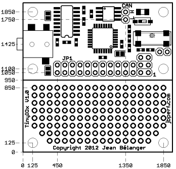
The board is 5cm by 5cm. The position of the mounting holes and headers is shown below; the units are in mils (thousandths of an inch) with the origin being the lowest left corner. The pad are on a 0.1" by 0.1" grid.
Using the lower left corner as pictured above as (0,0), the mounting holes are located at: (125,125), (125,1100), (125,1850), (1850,125), (1850,1100), (1850,1850). The split line between the 2 sides is at 950. JP1's lower left pad is at (450,1050), the CANL pad is at (1350,1750) and the top row on the proto area is at 850.
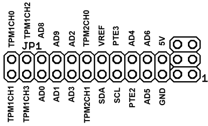
The pinout for J1 is shown below. This gives access to all the CPU input and output pins with the exception of the power, CAN bus and serial port pins.

TinyIOx V1.0 Pinout
- AD0 to AD9 are the 9 ADC inputs available (AD7 is not available because it is used as an emergency bootloader pin); these correspond to the PTA0 to PTA6 (AD0 to AD6) and PTB0 and PTB1 (AD8 and AD9).
- TPM2CH0 and TPM2CH1 are the timer 2 channels 0 and 1; these are the 2 timer channels that can be used as PWM outputs and they correspond to PTD0 and PTD1.
- TPM1CH0 to TPM1CH3 are the timer 1 channels 0 to 3; these are the 4 timer channels that can be used as PWM inputs and they correspond to PTD2 to PTD5.
- PTE2 and PTE3 are the 2 spare digital I/O pins.
- SCL and SDA are the I2C bus pins and correspond to PTE4 and PTE5.
- 5V and GND are used to power the board and need to be connected to a regulated 5V power supply such as the MS board 5V supply.
- VREF is connected to 5V by default (this is done by a solder jumper on the board so there is no need for an additional connection) and is used as the ADC reference; this can be used if a different 5V reference is required.
Firmware
The latest firmware and ini files can be found here.
The easiest and recommended way to upgrade the firmware is now to use the port scanner: port scanner. The legacy method is described below.
For upgrading the firmware, you need to use a Windows PC and CAN passthrough with an MS with either MS2/Extra or MS3. And you need to use the downloader tinyioxdl.exe which is included in the firmware zip file. If you are using an MS2/Extra with firmware 3.3.x or later or if you are using an MS3 with firmware 1.1.x or later you will need this downloader.
So, with the PC connected to the MS and the TinyIOx connected to the MS, you need to put tinyioxdl.exe and tinyIOx.s19 in the same directory, open a command window, go to the directory where the files are and type:
tinyioxdl COMx 115200 tinyIOx.s19
where COMx is the COM port used to connect to the MS.
Important note: You need to disable any CAN polling and CAN broadcasting done by your MS2 or MS3 before starting the firmware upgrade since there could be conflicts between the different message streams which would make the upgrade fail. Failure to do so will likely result in some sort of error and a partial upgrade that will disable the TinyIOx until a successful firmware upgrade.
Ordering
The assembled boards are available at US$85 per board plus shipping. Shipping for up to 2 boards is US$8.50. This is for regular mail from Canada in a bubble envelop which means there is no tracking, no insurance and no guarantee on the delivery time.
US buyers: Please note that, as of February 1st 2025, boards shipped to the US might be subject to a tariff. This will be charged to you by your government so we have no control on the amount or how and if this is charged to you. This is basically a sales tax on you, the consumer, by your own government.
Canadian buyers may want to contact me directly (orders at jbperf.com) for alternative payment options in Canadian funds, such as Interac, together with a lower shipping cost.
Sales are suspended temporarily due to the possible upcoming CanadaPost strike.
You can contact me through PM on the forum where my user name is jbelanger, at the msextra forum where my user name is racingmini_mtl or by email.
