Peak&Hold Injector Driver Board v2.0 for Megasquirt
Overview
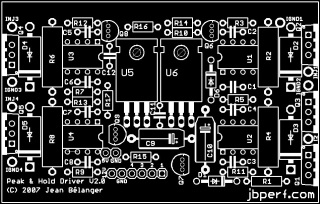
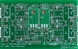
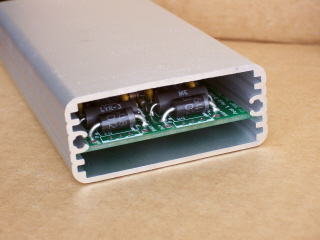
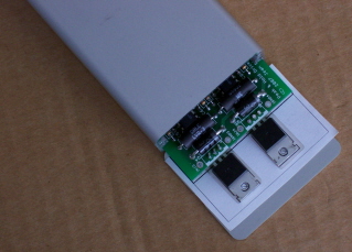
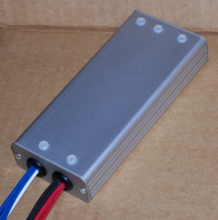
This is a preview of the v2.0 P&H board. Click on any picture for a larger version. The pictures with the connectors are there to show the size of some potential connectors compared to the case.
The BOM and the schematics will be provided with a board purchase. Reference to the connectors part numbers can be found on the second and third sheets of the BOM.
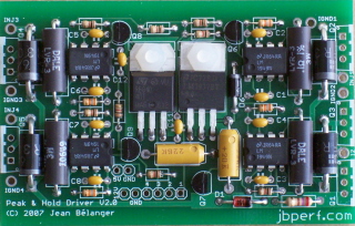
Partially assembled board. Need to add the 4 TIP122 and the TIP42.
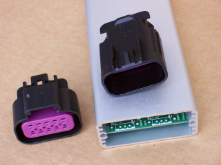
10-position GT150 Delphi male and female connectors
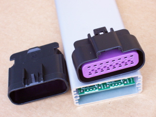
16-position GT150 Delphi male and female connectors
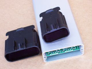
16-position and 10-position GT150 Delphi connectors
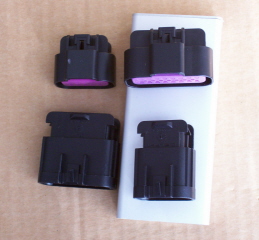
16-position and 10-position GT150 Delphi male and female connectors
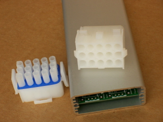
15-position Tyco/Amp Mate-N-Lok male and female connectors
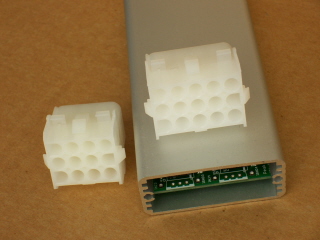
12-position and 15-position Tyco/Amp Mate-N-Lok connectors
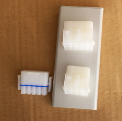
12-position and 15-position Tyco/Amp Mate-N-Lok male and female connectors
Assembly
- Install and solder Q6 to Q9 (2N3904 transistors). You want to install those first because they are easier to test with no other component installed on the board and the pads are very close together so the possibility of a solder bridge is higher.
Once they are installed, check that you don't have continuity between the 3 leads. Check that the base (middle pin) is connected to R14-17 (for Q6-9 respectively). Check that the emitter (pin 1) is connected to ground. Check that the collector is connected to pin 1 of U1-4 (for Q6-9 respectively).
Correct any solder bridge or cold solder that you observe from the checks and perform the tests and corrections until everything checks out. - Install and solder R1 (270Ω), R3, R5, R7, R9 (39KΩ), R10 to R17 (1KΩ).
- Install and solder D1 and D6.
- Install and solder C1 to C8, C11 (0.1µF), C12 (0.001µF; there is a '102' marking on it) and C9, C10 (22µF).
- Install and solder U1 to U4.
- Install and solder U5 and U6. Bend the leads so that the mounting holes align with the holes in the board and use the nylon screws and nuts to attach them ot the board.
- Install and solder R2, R4, R6, R8 (0.1Ω).
- Install and solder D2 to D5.
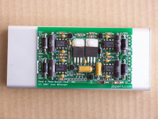
This is what you should have:
- Use the templates available for positioning the transistors for assembly. Bend the leads up to align the transistors with the template while making sure the board also aligns with the template. Print and cut the template as per the picture below and insert the board in the second slot of the case. Use the endplates to set the transistors at the correct height (same as the bottom of the case). Solder the transistors. Make sure you install the transistors in the correct position (Q1: TIP42C, Q2-5: TIP122)
- Use the template for case drilling to drill the mounting holes for the 5 transistors. Print the template and cut the template and position the template on the bottom of the case (printed side facing away from the board). Drill the mounting hole using a 1/8" (3.2mm) drill bit. Make sure to deburr and clean the holes; any swarf left could ground the transistor.
- Solder wires for the ECU injector signal (1 to 4) and for power supply (12V and GND) to the board. You can use 20 gauge wire for these.
- Solder wires for the injector control (INJ1, I2, INJ3, INJ4) and for the injector grounds (IGND1 to 4). You can use 18 gauge wire for these. Make sure to apply enough heat to allow the solder to flow on the pad and in the wire.
- At this time, it is a good idea to test the board. Connect a 12V supply and ground to the board. Check that you have 5V at the pad near the 12V input (the 5V pad (and the adjacent GND pad) is not use for anything other than testing).
Once you have checked that you have 5V on the board, you need to check the injector outputs:- Connect one injector ground to the same ground you use to power the board.
- Connect a LED and a current limiting resistor (1KΩ) to 12V and to one of the injector outputs (INJx).
- Ground the corresponding injector signal input.
- Do a trial fit of the board in the case: slide the board in the second slot and make sure that the 5 transistors line up with the corresponding mounting hole and that they lay flat on the bottom of the case. This is important because the case is used as a heat sink. Remember that Q2-5 need to use a mica insulator. If needed, you can gently bend the leads to align the transistors.
- Once alignment is checked, it is time for the final assembly in the case.
- Apply heat sink compound on the back of the metal tab on all five TO-220 transistor (Q1-5).
- Put the mica insulators on the back of the TIP122s (Q2-5) using the heat sink compound to make them stick. Align the insulators as best as possible.
- Apply heat sink compound to the back of the insulators.
- Gently lift all transistors by bending the leads slightly so that they don't drag on the bottom of the case.
- Slide the board in the second slot of the case until the transistors align with the mounting holes.
- Insert the screws from the outside of the case through the insulator (when applicable) and through the metal tab. Make sure the insulators are correctly aligned.
- Put the rest of the mounting hardware in the following order: shoulder washer (black plastic washer), plain washer, lock washer, nut. Make sure the shoulder washer is correcly centered inside the tab mounting hole. Lightly tigthen the nut.
- Check that there is no continuity between the metal tab of the TIP122s (Q2-5) and the case. If there is continuity, realign the mounting hadware.
- Re-do the board test to insure everything is still working as it should.
- One everything is checked, tighten more solidly the nuts. Do not over-tighten the nut so as not to crush the shoulder washer.
- Re-do the board test one more time.
- Drill one endplate to allow mounting the rubber grommets. Use a 3/8" (9.5mm) drill bit. Insert the rubber grommets in the holes.
- Slide the wires in the two rubber grommet until the endplate can be attached to the case. You can use one hole for the 12V supply and ground and the injector ECU signal wires (6 wires) and the other hole for the injector output and ground wires (8 wires). Attach the other endplate.
- You can leave the case bezels off but you may need to countersink the endplate mouting holes. This is what you should now have at this stage: Please note that the picture shows nylon screws but you should use steel screws as supplied in the kit.
- Install the connector(s) of your choice to the wires.
Congratulation! You now have a fully assembled Peak & Hold injector driver box.
Installation
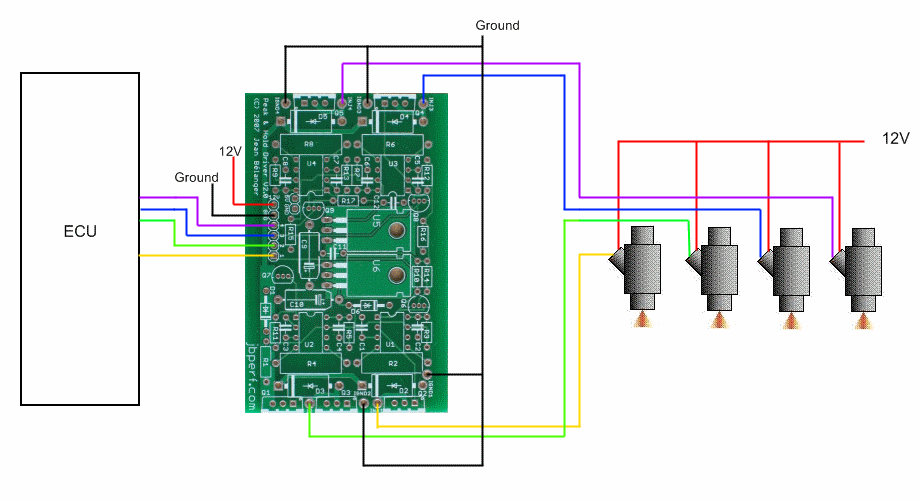
With the injectors connected to the ECU as follows:
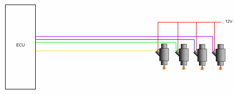
you need to connect the V2.0 board this way:
