JimStim v1.5 Assembly Instructions
Note: It is recommended to read through the entire page before starting assembly.
Assembly
- Install and solder R1 to R10 and R23 (330Ω).
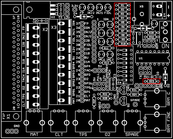
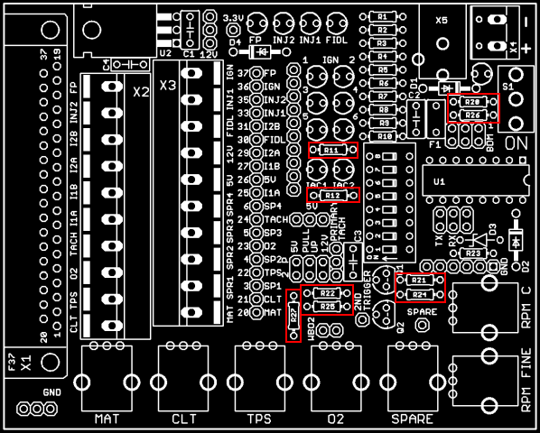
- Install and solder R11, R12, R20, R21, R22, R24, R25 (1KΩ), R26 (4.7KΩ), R27 (39KΩ).
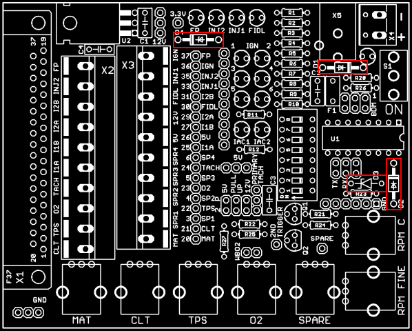
- Install and solder D1, D2 (1N4004 diodes), D3 (1N5226 Zener), and D4 (1N4729 Zener). Make sure that the banded side of D1 is towards S1, the banded side of D2 is towards the CPU, the banded side of D3 is towards the DB37, and the banded side of D4 is towards C1.
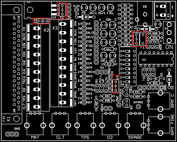
- Install and solder C1 (10µF), C2 (0.22µF), C3 and C4 (0.1µF). Install and solder polyfuse F1 (besides C2).
- Install and solder the 11 red LEDs and the 2 bicolor LEDs. Install the bicolor LEDs at locations IAC1 and IAC2. All short leads must be on the left when looking at the picture below (DB37 side).
To have evenly positioned LEDs, you can apply solder to one lead then hold the tip of the soldering iron to the LED's lead, straighten the LED, move the iron tip away from the lead, and hold until the solder sets back. Let it cool down and you can then solder the other lead. Make sure to not hold the iron tip too long on the LED's lead. More than a few seconds and you risk overheating the LED. If the LED is not straight, let it cool until you try to straighten it again.
You can do one lead of a few LEDs at a time, straighten them out, and then solder the other leads. This will give enough time for the LEDs to cool down between heat applications.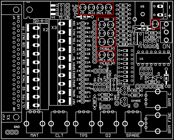
- Install and solder the processor socket. Make sure that the notch in the socket matches the notch on the board silkscreen.
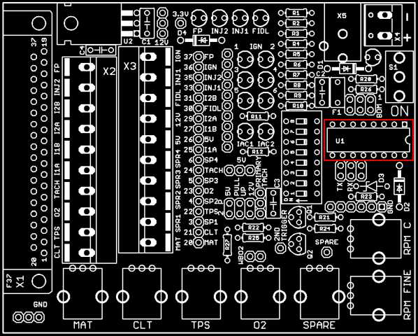
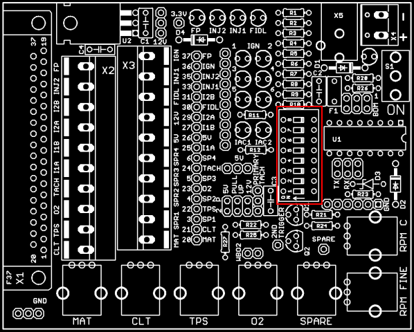
- Install and solder the 8-position DIP switch.
- Break away the single row pin header to have: 1 19-pin section, 1 10-pin section, 1 6-pin section, 4 3-pin sections, 1 2-pin sections, and 3 individual pins. Break away the dual row pin header to have 3 3x2 sections. To break away the smaller sections cleanly, you can use a pair of pliers.
If your kit came with pre-cut headers of the correct length, place them where appropriate.
Install and solder all the pin header sections. To keep the pin headers straight, use the same technique as described for the LEDs in step 5. Be careful not to touch the pin being heated by the soldering iron with your bare skin because the pin will become very hot. For the small headers (3, 2, and 1-pin sections) this is rather difficult unless you keep something between your fingers and the pins. You can use a few layers of fabric tape or even a piece of folded paper. Do not use anything that could melt because it could stick to your finger if it melts and cause some burns.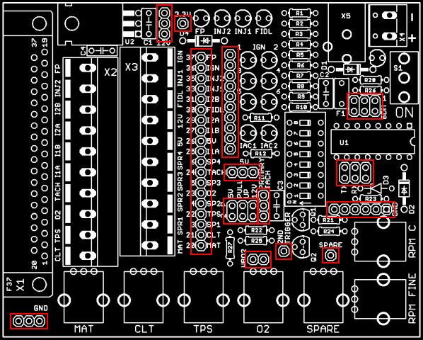
- Install and solder Q1 and Q2. To install them you will have to bend the middle lead 90 degrees back and the another 90 degrees down as shown here:

Each straight section is about 1/8 inch.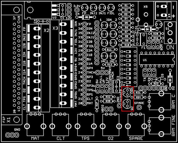
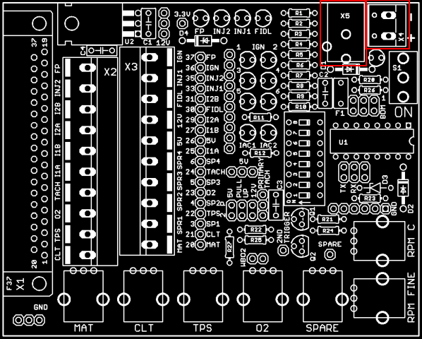
- Install and solder the 2-position terminal block (X4). Install and solder the power jack (X5).
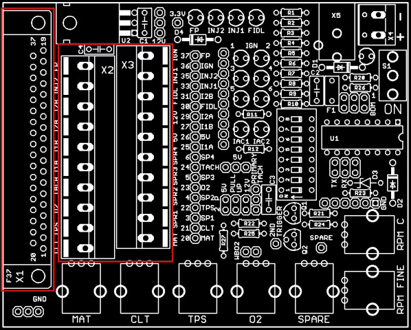
- Install and solder the 2 10-position terminal blocks (X2 and X3). Install and solder the DB37 connector (X1).
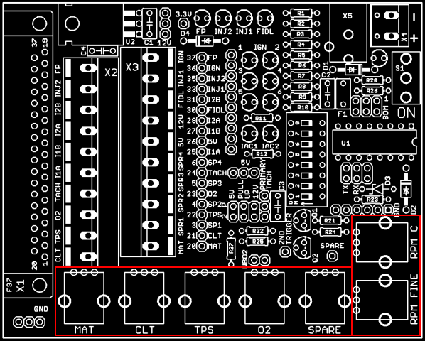
- Install and solder the 7 potentiometers.
- Install and solder the toggle switch (S1). Install and solder U2 (voltage regulator). Bend the leads so that U2 can lay on the board with the metal tab against the board and that the hole on the tab aligns with the hole in the board. You can attach U2 to the board if you have a screw and nut.
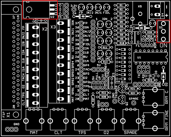
Making the JimStim ready for use
The final step is to install the processor in the socket. Make sure to install it such that the notch matches the notch on the socket (facing away from the DB37).
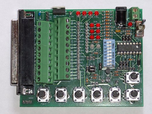
This completes the assembly of the JimStim. To use the stim, power must be applied to either the power jack or the 2-position terminal block and the toggle switch switched to the ON position (as indicated on the board). Any DC power supply that can generate from 9V to 14V and from 300mA to 1000mA will work fine. Less than that might not be enough to correctly run the JimStim and the MegaSquirt board. More voltage than that might be too much for either the JimStim or the Megasquirt board and more amperage capability (such as a 12V battery) might be enough to actual put either board on fire if there is a malfunction. A low-amperage fuse is mandatory in the latter case. The power jack is for a 2.1mm ID, 5.5mm OD connector and the positive voltage must be in the inside and the ground on the outside part of the connector. The screw terminal has + and - marks for the correspnding power polarity.
The switch controls power to both the JimStim and the MegaSquirt board and the LED besides the switch indicates when power is ON. To send a tach signal to the Megasquirt board, a jumper must be installed on the primary tach pin header. For complete setup information, refer to the JimStim Firmware v2.0 page.
Important: Make sure that the JimStim is not resting on a conductive surface and that no conductive material touches the bottom of the board when powering it up. Failure to do so may lead to electrical shorts and part failures. Also, take the normal precautionary measures regarding static electricity when handling electronic components.
Testing and Troubleshooting
Testing the LEDs
The power LED should light up when power is applied to the JimStim and the power switch is switched on.
To check that the other red LEDs are functioning as they should, do the following:
- Disconnect the JimStim from the MegaSquirt
- Make sure the JimStim is resting on a non-conductive surface and nothing conductive touches it
- Connect the 3.3V pin header to one of the pins on the 3-pin 5V header using a wire jumper. Warning: Make sure that this is only done with the MegaSquirt disconnected from the JimStim otherwise the JimStim processor will suffer permanent damage. Disconnect the wire jumper immediately after the test as a precaution.
- Connect a wire jumper to one pin of the 3-pin ground header and connect the other end to the first pin (closest to the injector LEDs) of the 10-pin LED header
- Connect power to the JimStim and switch on: the first ignition LED should light up.
- Repeat the previous 2 steps to test the other ignition LEDs using the pins 2 to 6 of the 10-pin LED header.
- To test the FP, INJ1, INJ2, FIDL LEDs, repeat the same steps but use the corresponding pins on the 19-pin header instead of the 10-pin LED header.
Warning: Once the LED testing is done, disconnect the wire jumper from the 3.3V pin header to the 3-pin 5V header immediately. Failure to do so will result in permanent damage to the JimStim processor.
To test the IAC LEDs, connect pin 7 of the 10-pin header to 12V and pin 8 of the 10-pin header to ground to test IAC1 and pin 9 and 10 to test IAC2. Reverse the polarity to check the other color.
Testing the tach signal
If the Jimstim voltage regulator and/or CPU and/or the polyfuse are getting hot when power is applied, refer to the next section (Troubleshooting tach signal, CPU and 3.3V).
Testing of the tach signal can be done using the LEDs. This test will also verify that the Jimstim CPU is working correctly. To do this you need to do this:
- Power off the JimStim and disconnect it from the MegaSquirt
- Remove the pull up jumpers
- Remove the primary tach jumper
- Set the wheel mode to distributor mode (all DIP switches off)
- Connect a wire jumper from the primary tach header (where the jumper usually goes) to an IAC led. Use the primary tach header pin closest to the pots (away from the PRIMARY TACH text) and the last pin of the 10-pin header (pin closest to the pots)
- Connect a wire jumper from the other side of the IAC led to 12V. Use the next to last pin on the 10-pin header (just besides the pin connected in the previous step) and one of the pins on the 3-pin header besides the voltage regulator.
- Turn the RPM pots all the way counterclockwise.
Once the connections above are done, power up the JimStim (with the MegaSquirt still not connected) and start slowly turning the RPM FINE potentiometer clockwise. You should see the led start flashing and it will flash faster as you turn the pot more.
Warning: With the JimStim not connected to the MegaSquirt, the bottom of the board will rest on a surface with all the exposed leads and solder pads. Make absolutely sure that the surface is non-conducting and that there is nothing that could make a short also on the surface. A short may cause permanent damage to the CPU and possibly other components.
If the LED does not flash, there is a problem with the JimStim CPU or the board. Go to the next section for troubleshooting. If the LED does flash, the board and CPU are fine. Remove the wire jumpers and put back the needed jumpers before connecting to the MegaSquirt.
To test the second trigger signal, do the same test as above but use the 36-1 wheel mode (only DIP switch #3 on) and connect the LED to the 2nd trigger pin header.
Troubleshooting tach signal, CPU and 3.3V
If the JimStim voltage regulator and/or CPU and/or the polyfuse are getting hot when power is applied, it is possible that there was a short on the 3.3V. This may have resulted in a failure.
The verification steps are as follows:
- Remove the CPU and see if the voltage regulator still gets hot.
If it still gets hot, then check the protection diode: remove one lead from the board and power up the JimStim.
If the voltage still gets hot then you have a short on the board
if not, then the diode has failed and you need to replace it.
If the voltage regulator does not get hot, the CPU has likely failed due to a short on the 3.3V rail and it will need to be replaced. - Once you know that the voltage regulator, the protection diode are correct, you will need to check the voltage at the CPU socket. Make sure you have 3.3V at pins 1 and 3, pins 13 and 14 voltage depending on the RPM pots position (0V to 3.3V), and that all the other pins are either floating or at 0V. If this is not the case then there is a problem with the board.
- If step 2 checks out ok, put the CPU back in the socket and perform the tach signal test above. If you are not sure that the LEDs are functional, perform the LED test above before doing the tach signal test.
To be completed.