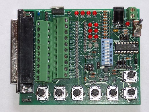
JimStim v1.3 Assembly Instructions
Note: It is recommended to read through the entire page before starting assembly.
Assembly
- Install and solder R1 to R10 and R23 (330Ω).
- Install and solder R11, R12, R20, R21, R22, R24, R25 (1KΩ), R26 (4.7KΩ), R27 (39KΩ).
- Install and solder D1, D2 (1N4004 diode)
and D3 (3.3V Zener). Make sure that the banded side of D1 is towards the DB37, the banded side of D2 is towards the CPU,and the banded side of D3 is towards the DB37. Important: Do not install D3. There is an issue with D3 that is being investigated. This will not limit the functionality of the JimStim. If the serial-USB cable is to be used, make sure that the cable is correctly installed because the D3 diode is for reverse polarity protection. This protection is no longer there when D3 is removed/not installed. - Install and solder C1 (10µF) and C2 (0.22µF).
- Install and solder the 11 red LEDs and the 2 bicolor LEDs. Install the bicolor LEDs at locations IAC1 and IAC2. All short leads must be on the left when looking at the picture below (DB37 side).
To have evenly positioned LEDs, you can apply solder to one lead then hold the tip of the soldering iron to the LED's lead, straighten the LED, move the iron tip away from the lead, and hold until the solder sets back. Let it cool down and you can then solder the other lead. Make sure to not hold the iron tip too long on the LED's lead. More than a few seconds and you risk overheating the LED. If the LED is not straight, let it cool until you try to straighten it again.
You can do one lead of a few LEDs at a time, straighten them out, and then solder the other leads. This will give enough time for the LEDs to cool down between heat applications. - Install and solder the processor socket. Make sure that the notch in the socket matches the notch on the board silkscreen.
- Install and solder the 8-position DIP switch.
- Break away the single row pin header to have: 1 19-pin section, 1 10-pin section, 1 6-pin section, 3 3-pin sections, 2 2-pin sections, and 3 individual pins. Break away the dual row pin header to have 3 3x2 sections. To break away the smaller sections cleanly, you can use a pair of pliers.
If your kit came with pre-cut headers of the correct length, place them where appropriate.
Install and solder all the pin header sections. To keep the pin headers straight, use the same technique as described for the LEDs in step 5. Be careful not to touch the pin being heated by the soldering iron with your bare skin because the pin will become very hot. For the small headers (3, 2, and 1-pin sections) this is rather difficult unless you keep something between your fingers and the pins. You can use a few layers of fabric tape or even a piece of folded paper. Do not use anything that could melt because it could stick to your finger if it melts and cause some burns. - Install and solder Q1 and Q2. To install them you will have to bend the middle lead 90 degrees back and the another 90 degrees down as shown here:

Each straight section is about 1/8 inch. - Install and solder the 2-position terminal block (X4). Install and solder the power jack (X5).
- Install and solder the 2 10-position terminal blocks (X2 and X3). Install and solder the DB37 connector (X1).
- Install and solder the 7 potentiometers.
- Install and solder the toggle switch (S1). Install and solder U2 (voltage regulator). The metal tab is facing outside the board.
Making the JimStim ready for use
The final step is to install the processor in the socket. Make sure to install it such that the notch matches the notch on the socket (facing away from the DB37).
This completes the assembly of the JimStim. To use the stim, power must be applied to either the power jack or the 2-position terminal block and the toggle switch switched to the ON position (as indicated on the board). Any DC power supply that can generate from 9V to 14V and from 300mA to 1000mA will work fine. Less than that might not be enough to correctly run the JimStim and the MegaSquirt board. More voltage than that might be too much for either the JimStim or the Megasquirt board and more amperage capability (such as a 12V battery) might be enough to actual put either board on fire if there is a malfunction. A low-amperage fuse is mandatory in the latter case. The power jack is for a 2.1mm ID, 5.5mm OD connector and the positive voltage must be in the inside and the ground on the outside part of the connector. The screw terminal has + and - marks for the correspnding power polarity.
The switch controls power to both the JimStim and the MegaSquirt board and the LED besides the switch indicates when power is ON. To send a tach signal to the Megasquirt board, a jumper must be installed on the primary tach pin header. For complete setup information, refer to the JimStim v1.3 Setup page.
Important: Make sure that the JimStim is not resting on a conductive surface and that no conductive material touches the bottom of the board when powering it up. Failure to do so may lead to electrical shorts and part failures. Also, take the normal precautionary measures regarding static electricity when handling electronic components.
