Fuel Injecting the A-Series
 Many have tried to fuel inject the A-Series but few have delivered success. The factory first developed the SPi system i.e. Single Point injection and lastly the MPi i.e. Multi Point injection. The term Multi Point refers to port injection which involves a controlled injection of fuel for each cylinder.
To understand the problems of port injecting the A-Series, it is first necessary to understand some basic features of fuel injection:
Fuel is delivered by injectors, fed at high pressure. An Electronic Control Unit (ECU) controls the opening and closing of the injectors to meet the demand of the engine. The ECU calculates the fuel requirements from the speed of the engine, the inlet manifold pressure/vacuum and the air temperature. Hence, the ECU delivers the correct amount of fuel to create the optimum Air Fuel Ratio (AFR) within the cylinder.
The injectors fire slugs of fuel into the inlet manifold, unlike a carburettor that continuously adds fuel to the air stream. This slug of fuel does not have a chance to atomise within the manifold alone and hence does not fully mix with the surrounding air before entering the cylinder.
In a conventional 4 cylinder engine with four inlet ports, the slug of fuel is delivered to each cylinder once every engine cycle: 2 revolutions which include the 4 strokes - intake, compression, combustion and exhaust. Most OEM fuel injection systems fire all four injectors at the same time irrespective of the current stroke of the cylinder. It doesn’t really matter as the correct amount of fuel will go into the cylinder, either from this slug, the preceding one or the next. As long as the injectors fire the correct amount of fuel it will get into the cylinder.
The difficulty with port injecting the A Series is that the intake ports are siamesed, so cylinders 1 & 2 share an inlet port as do 3 & 4. Let’s call the ports A & B. The firing order of the A Series is 1342 which can be written 2134, same thing. Hence the inlet ports feed two cylinders in quick succession AABB. Each intake port sees two intake strokes, inner cylinder then outer cylinder during a single revolution of the engine and then nothing in the next revolution and so on.
Hence, a slug of fuel fired into the inlet port arbitrarily has a 75% chance of going into the inner cylinder and only a 25% chance of going into the outer cylinder.
It then follows, that the only way to ensure that the outer cylinder gets enough fuel is to deliver the precise amount of fuel over a very short period at a particular point in the engine cycle.
Going back to the conventional engine, the injectors are normally sized to open for up to 80% of the engine cycle i.e. more than 3 of the 4 strokes. The A-Series has only a very short window to inject the outer cylinder, so the injectors need to be rated to deliver in around 20% of the engine cycle, four times larger than normal conventional engines.
To ensure that the fuel enters the cylinder at the precise point, the ECU needs to know at which point of the engine cycle each cylinder is at. This is achieved with a cam sensor in addition to the usual crank speed sensor. As the cam rotates at half the engine speed, the cam signal can set the injection point to the correct stroke.
The ECU then needs to be able to time the injection to a precise point, much the same as ignition timing. Very few ECUs have this ability, but the Megasquirt MS2/Extra code now has this facility thanks to the work of Jean Belanger and the TurboMinis.co.uk forum.
Trials
 Initially, a 1275 MG Metro engine was fitted to my ’93 Mini Sprite. The LCB legs were fitted with bosses to fit wideband oxygen sensors that give an accurate reading of the engine Air:Fuel ratio (AFR) over a wide range.
The engine was freshened up and fitted with a mildly ported SPi head, SW5 cam and MG Metro LCB style exhaust manifold.
We used the Innovate range of products initially. An Innovate LC-1 and gauge was fitted to the leg of the LCB that takes the flow from the inner cylinders and a portable Innovate LM-1 was used on the other LCB leg for the outer cylinders. We also fitted an Innovate LMA-3 Aux Box that provided monitoring of engine vacuum and rpm. The various components were daisy-chained together to communicate over a serial link to a laptop for data-logging purposes.
The first run was made in December 2007 using a HIF44 carburettor and MG Metro inlet manifold to test the system and to baseline the data. Interestingly, the carburettor did not provide equal AFRs to the inner and outer cylinders. The inner cylinders were found to run much richer than the outers. There was approximately 1.5 AFRs difference at cruising speeds, although it evened out by 5000rpm.
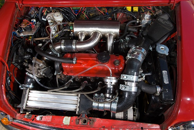
 A fabricated inlet manifold fitted with four MPi injectors and a Ford RS throttle body was then fitted and wired up to the Megasquirt MS2 ECU. The ECU directly controls a Ford coil pack for ignition.
The first EFi trials were carried out using the standard MS2/Extra code and gave reasonable results, but with a very wide spread of AFRs as expected. However, driveability was good with just a slight hesitation at cruise. The outer cylinders were running extremely lean.
We then loaded the first version of the special code written by Jean Belanger following discussions on the TurboMinis.co.uk forum. This first version of the code worked in a semi-sequential mode. It injected fuel into each port once each revolution at a pre-determined point in the engine cycle. The injection timing was arranged to coincide with the open inlet valve of the outer cylinder in each port. Hence in one port, the fuel would enter the outer cylinder through the open inlet valve. In the other port the fuel would be injected into the ‘dead’ port and be available for the inner cylinder, 180 degrees later. On the next revolution, the same injection would take place, but the other outer cylinder would get the directly injected fuel.
Although this system was a great step forward from the standard code, we were not satisfied that the AFRs were accurate enough to what we required for a turbo-charged engine. After trying many different injection timing combinations, we were unable to get equal AFRs through out the operating range of the engine. We concluded that the fuel injected into the ‘dead’ port had time to atomise and excluded air from the port which made the inner cylinders run rich. Whilst atomisation of the fuel is not a bad thing, with different degrees of atomisation occurring for the different cylinder pairs, this was causing the spread of AFRs.
In mid 2008, the engine was changed to the 998 that currently sits in the car, but without the turbo-charger. Further trials took place with different injectors and other modifications, but no real progress was made.
It was eventually concluded that we needed to develop the ECU code further to provide better control of the injection timing to directly inject into each cylinder. This then required the ECU to synchronise with the engine inlet strokes. Therefore we constructed a Cam Sensor from an old distributor fitted with a hall sensor. The cam sensor ensures that the ECU knows when No. 1 cylinder is on it’s inlet stroke, rather than the power stroke.
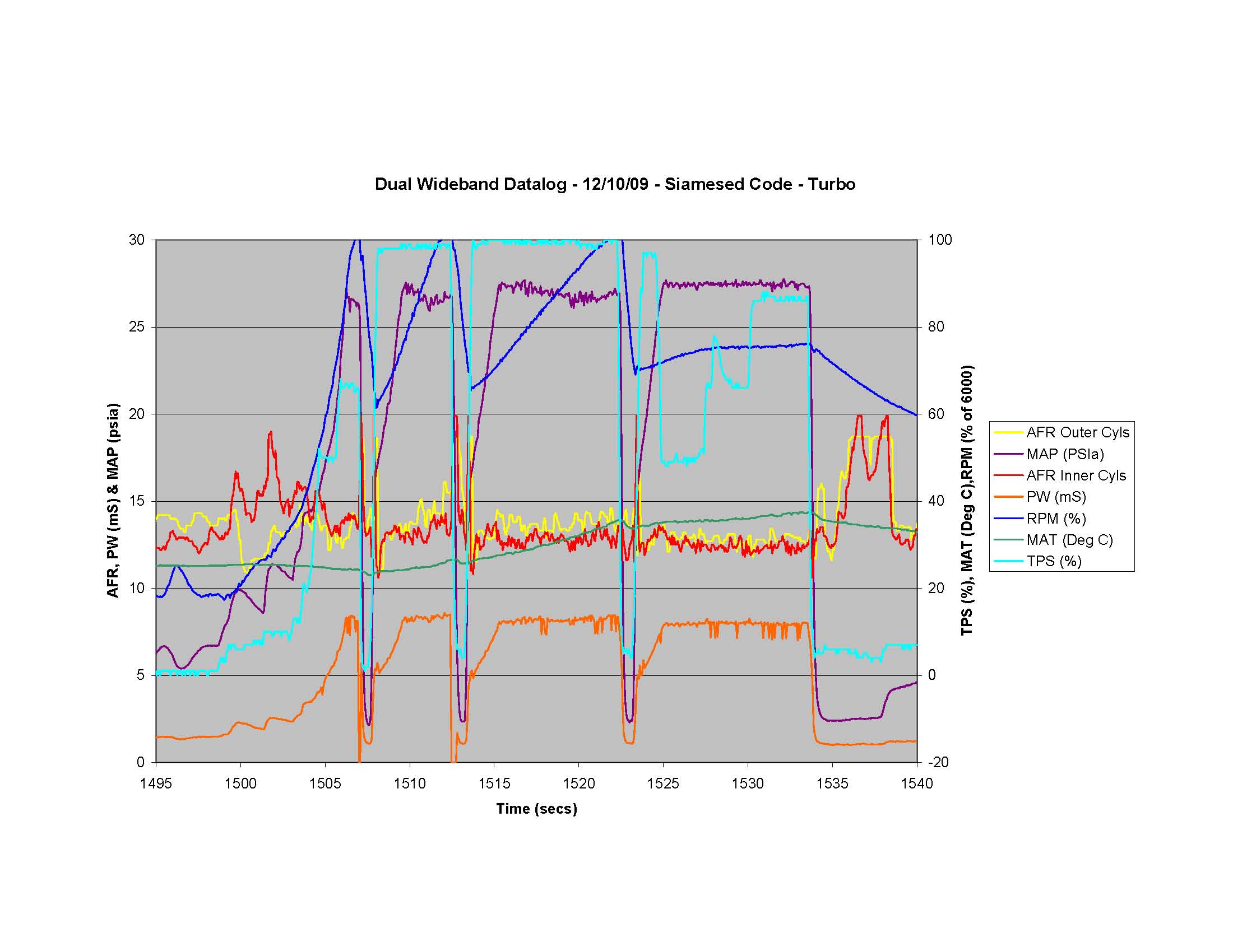
At this time we also fitted further instrumentation to monitor Exhaust Gas Temperature (EGT) and Cylinder Head Temperature (CHT). This was done by thermocouples and an Innovate TC-4 that was linked into the daisy-chain. The primary purpose of this was to establish if there was a correlation between any of the temperatures and AFRs. As wideband sensors do not like operating upstream of a turbocharger due to the pressure in the manifold, we needed to develop an AFR monitoring system when under boost.
 Jean developed the code and this was uploaded to the car in February 2009. By June, we had made further developments to the code following testing and had a working system in which we could get very close control of the AFRs in each cylinder over the full operating range.
Unfortunately we had also found that the temperature monitoring did not provide any useful data. The CHTs were too slow to react and the EGTs were so much higher for the inner cylinders, due to the siamesed exhaust port, that the data was unusable. We therefore needed another method of measuring AFRs with the turbo-charger in place.
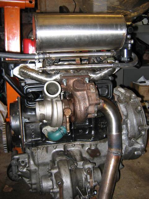
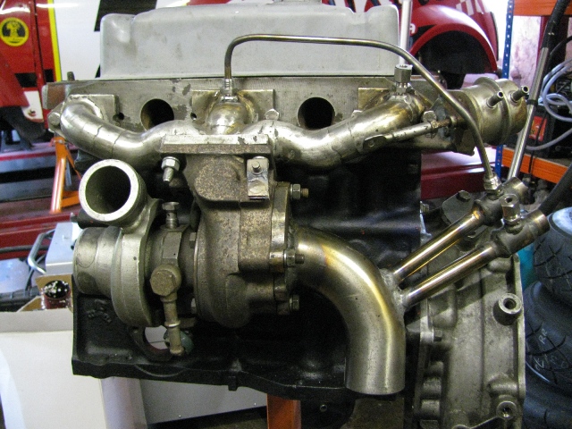
Following on from an idea originally posted on the TM forum, we constructed a sample chamber for each wideband sensor. The chambers are fed by a 4mm bore pipe connected to the manifold near to the head flanges. The chambers are also connected by a 12mm bore pipe to the downpipe after the turbo-charger. Hence the chambers are fed with exhaust gas from individual ports but operate at normal pressure.
 Hence, the temperature instrumentation was removed. Around this time, the Innovate LMA-3 failed and we started having problems with the connector on the Innovate LM-1. Not surprising after all the abuse. The instrumentation system was refined to what we now have fitted in the car which is the original Innovate LC-1 and gauge plus an AEM gauge. These both feed a 0-5v signal to the ECU and all data is logged from the ECU.
The turbo-charger was fitted to the car the weekend before the British Mini Showdown in July. We very quickly developed the fueling, ignition and injection timing setting for boost and the car was driven to Avon Park.
Further development to achieve consistently equal AFRs at each cylinder under all conditions is on-going.
The code is now incorporated in the latest alpha release of the MS2/Extra code, version 3.0.3 which can be downloaded from the MSExtra forum.
Paul Sturgess, October 2009.